Categories
Residential Electricity 101 Switch Wiring

4 Way Switch Wiring Methods

If you only need one switch to control a light, then you would use a single pole switch.
If you need 2 switches to control a light then you would use two 3way switches.
If you need three switches to control a light then you would use two 3ways with one 4way.
If you still need more switches just add 4ways. Need six switches? Use two 3ways with four 4ways.

➳ Weather you use one 4 way or more, the 4 way will not work without two 3 ways.

A 4way switch has 2 “IN” terminals and 2 “OUT” terminals. They are identified on the switch with the words “IN” and “OUT” or there might be 2 marks identifying a pair of terminals as either “IN” or “OUT” The 2 traveler wires from one 3way are connected to the 2 “IN” screws or the 2 “OUT” screws but never one traveler to “IN” and the other to “OUT”

S4 Method #1     Basic 4Way

This is the best and easiest method of wiring 4 way switches.
If you only learn one 4 way method, learn this one.
Rating  Excellent A+ ☺
The most simple and trouble free 4 way method.
Level  Intermediate. It is also called a “Plain Jane 4 way”
Description  Same as 3way Method #1 but add a 4way switch into the traveler wires between the two 3ways.  A 2 wire (14/2, 12/2) feed is pulled from the nearest source of power like a receptacle to the first 3way switch box. Then a 3 wire (14/3, 12/3) is run between switches, from the first 3way to the 4way to the second 3way. Finally a 2 wire switch leg is pulled from the last 3way to the nearest light and then to any other lights that are supposed to come on with these switches.
L1 = hot, C = common, T = traveler terminal, IN = the IN terminal on a 4way switch, OUT = the OUT terminal on a 4way, and N = neutral.

L1 ➪ C1 ➪ 2 ➪ 4 ➪ 7 ➪ 9 ➪ C10 ➪ 11 ➪ 12 ➪ N

Current begins at L1 and flows through the wire to C terminal on the first 3way switch. Inside the switch it flows through the switch blade (purple) from C1 to 2. It then leaves the 2 terminal and follows the (red) wire to IN terminal4 on the 4way switch. Inside the 4way current moves through the (purple) switch blade from IN to OUT terminal (never IN to IN or OUT to OUT) It leaves the 7 OUT terminal and follows the black wire to the 9 terminal on the last 3way switch. Inside the 3way it flows from 9 to 10 Common. It then leaves the 10 C terminal and follows the (black) switch leg wire to the 11 terminal on the light where it connects to a small point on the base shell of the light bulb. Inside the light bulb current flows through the filament wire to the base shell where it connects to terminal 12. From12 current heads back to the source through the neutral wire to N.
The part that is not shown is how current continues from the N (neutral) to a transformer coil, through the coil to L1 (hot) where it starts all over again.
As mentioned at the top, it is important to note how the 3way and 4way terminals make connections in different positions of the switch. In 4ways In’s connect to OUT’s but never to each other (unless the switch is defective).
In 3 ways Travelers connect to the Common but never to each other. Refer to the drawings above;
On the S4; 4IN connects to 6OUT or 7OUT but never the other IN number 5
5IN connects to 6OUT or 7OUT but never the other IN number 4
6OUT connects to 4IN or 5IN but never the other OUT number 7
7OUT connects to 4IN or 5IN but never the other OUT number 6

On the S3; 10 Common connects to 8 Traveler or 9 Traveler but 8 and 9 never connect together.

S4 Method #2    Dead End 4way With Extended Switch Leg

Rating  Above Average B 
This method is commonly used by professional electricians
Level  Intermediate.
Description   Power and switch leg at one 3 way and the dead end of a 3 wire at the other 3 way.  When wiring a dead ends you have a choice of which wire to extend over to the common on the dead end 3way switch:
– either extend the black switch leg from the light
– or extend the black hot (L1).
In this example the switch leg is extended over to the common on the dead end 3way.

S4 Method #2.1      Dead End 4way With Extended Hot

Rating  Above Average B  
Level  Intermediate
Description  Power and switch leg at one 3 way and the dead end of a 3 wire at the other 3 way. The travelers are the same as S4 Method #2, the neutral is the same, the only change in wiring is the hot is extended over to the dead end 3way’s common instead of the switch leg. Compare the L1 wire in this method with  the L1 wire in S4 Method #2 above.
 S4 Method #3      Double Dead End 4way
Rating   Average C+ 
Level  Advanced Also called a “Switch Leg and Feed at the 4way”
Description  Everything is pulled to the 4way switch box;
✓the feed, ✓the switch leg from the light, ✓a 14/3 from one dead end 3way and
✓another 14/3 from the 2nd dead end 3way.
The hot is extended to one 3way and the switch leg is extended to the other 3way.
S4 Method #4      4way with Two Wire Travelers
Rating  Above Average B 

Level   Advanced
There is a danger of overloading a neutral if 2 different circuits are used and those 2 circuit breakers are on the same phase (or same service hot or same transformer winding).

➳ Be certain the 2 receptacles and all switches used in this method are on the same circuit breaker.
Also there is a possibility of creating impedance if the 2 wire traveler cable is not run close to or along side with the 2 wire power cable. Impedance can cause slight noise interference with sensitive electronics.
This method uses only 2 wire cable like 14/2 or 12/2
If you have no 14/3 or 12/3  and don’t want to buy some then it is good to know this 2 wire method.
Description   Power, a hot and a neutral, is at both ends (both 3 ways). The switch leg from the light is at one end. A 2 wire, either 14/2 or 12/2, is run from the 3way to the 4way to the last 3way and is used as travelers. The hot at one end is connected to the common terminal on the 3way while capping off the unused neutral. At the other end, the black from the light’s switch leg is connected to the common terminal on the 3way. Also the white from the light’s switch leg is connected to the neutral from the power feed while capping off the unused hot.
S4 Method #5        Four Wire 4way

Rating   Above average B 

Level   Advanced

This is another method that uses only 2 wire and is good to know if you have no 14/3 or 12/3. But again, there is a possibility of creating impedance if the 2 wire traveler cable is not run close to or along side with the 2 wire power cable. Impedance can cause slight interference with sensitive electronics.

Description  Power is fed to the 3way at one end and the switch leg is run to the 3 way at the other end. A 2 wire (14/2 or 12/2) is used as travelers between each switch from the first 3 way to the 4 way and from the 4 way to the 2nd 3 way. A second 2 wire is run from the first 3 way passing through the 4way switch box and on to the 2nd 3 way where the white is used to feed the neutral to the light and the black is capped off.


.


 S4 Method #5.1      Four Wire 4way with lights at both ends
Rating   Average C  
Level   Advanced.
Another method using only 2 wire and creating impedance if the 2 wire traveler cable is not run close to or along side with the 2 wire power cable. Impedance can cause slight interference with sensitive electronics.
Description  Power is fed to the 3way at one end. A 2 wire (14/2 or 12/2) is used as travelers between each switch from the first 3 way to the 4 way and from the 4 way to the 2nd 3 way. The switch legs are at both ends. The switch leg from one light is run to the first 3 way and a switch leg from another light is run to the other 3 way.  A second 2 wire is run from 3 way to 3 way passing through the 4way switch box and used as a switch leg interconnecting both lights.Notice that there is a neutral in each switch box but only the first 3way at the left has an unswitched hot. Meaning that it is the only box you could tap into the wiring to add a receptacle. You can add another light, if needed, at the 4way by tapping into the black and white switch leg wiring that passes through the 4way switch box.


S4 Method #6 Light Fed 4way
Rating  Poor F 
Too many connections at a difficult location to access; the light on the ceiling.
Also, there is no neutral at the switch boxes.
Level  Advanced

Description  Power is fed to the light’s box up on the ceiling. A 3 wire is run from the light box to one dead end 3way. Another 3 wire is run from the light box to the 4way and from the 4way to the other dead end 3way.

The black wire from the feed is extended from the light box to the common terminal screw on one 3way. The black from the light’s switch leg is extended from the light box through the 4way switch box to the common terminal on the other 3way. The red and white wires are used as travelers going from the 2 traveler terminal screws on one 3way through the light box to the “in” terminals on the 4way. And again from the 4way “out” terminals to the 2nd 3way traveler terminals.
Key points;

– You choose the best location for the 4 way switch.

– There are no S4 dimmers If you have 3 (or more) switches controlling a light and the owner wants one of them to be a dimmer then be sure to pull wire in such a way that the dimmer location is a 3way not a 4way location
Categories
Residential Electricity 101

Life as a Residential Electrician

Life as a Residential Electrician.                                                                                                                     

Homepage

To become a professional Residential Electrician in America you need to learn;
➪ The National Electrical Code; A book of electrical rules commonly called the NEC or “the code” covering topics like; calculating box fill, GFI required outlets, stapling requirements, allowable ampacity….

➪ The science of electricity: Atoms, neutrons, protons, conductivity, insulator, induction…

➪ Basic electricity: DC and AC circuits, switch wiring diagrams, motors, transformers.
➪ Math as used in Ohms law.
➪ Basic architecture Knowing  how a house is built  will make electrical decisions easier. Communicating with other trades requires a knowledge of the names of different parts and areas of a house; header, cripple, joist, pocket door, footing, fire block, load bearing wall, foyer, pantry, living room, family room, hearth room.

➪ Basic conduit bending: Learning the 4 basic bends will cover most residential needs. 1) 90 degree bends 2) offsets 3) kicks and 4) saddles, both 3 point and 4 point saddles

Work place safety and the use of power tools and hand tools.The most difficult of these is the NEC, a book of rules that is updated and changed every 3 years. You must learn the NEC in order to pass a Journeyman electrical exam. Most areas of the country require you to work 4 years as an Apprentice before you can take the NEC test to receive your electrical Journeyman license and another 4 years as a Journeyman before you can take the NEC test to become a Master Electrician and start your own electrical company.2 of the best instructors for studying “the code” and pass an electrical license exam are;

Electrical work comes in a variety of specialized fields. Most people wrongly assume that electricians are experts in all these fields, but they are not. An experienced electrician in one field would need assistance performing the duties in another.

   For example, a Lineman Electrician, who works on high voltage cross country transmission lines, might have a difficult time trying to wire a 4 way switch in a new home. Wiring complicated switches is a common duty for Residential Electricians but it is not something a Lineman is expected to know.
An experienced Residential Electrician would not be allowed to work on high voltage transmission lines without passing the utility’s training course and then working under the supervision of an experienced Lineman for a period of time.
   Those who choose to be a residential electrician, find it very rewarding in many ways;
◈ Learning skills that can be used on your house and that of your family or friends.

◈ Work in a variety of locations, from the trailer park to gated mansions.

◈ Country estates in the middle of a cattle ranch, the private home of famous people, log cabins, apartments, townhomes, houses on the beach or up in the mountains.
◈  Being a part of a team that turns a vacant piece of ground into a beautiful home.
◈ Helping people improve the appearance, comfort or safety of their house.
◈ Learning skills that can open up opportunities in other fields of electrical work.
◈Watching a new house transform from an empty shell to a place someone will call home as shown below;

An arched hallway before…

…and after. Just a few things missing; base trim carpet and furniture.


Job Description for Residential Electricians

    Residential Electricians install and repair the electrical systems in houses and multifamily buildings from the outside electrical service wires to the inside receptacle including appliance or equipment connections . They learn and follow national and local electrical codes.

>They install switches, receptacles, wiring, lights, fans, circuit breakers, microwaves, cook tops and many other electrical items that are found in a house.
>They repair or replace switches, receptacles, circuit breakers, lights and many other electrical items that are installed in a house.
> Some Residential Electricians install phone, cable TV and door bell wiring and
garage door opener wiring.
> Occasionally they will install outdoor landscape lighting.
> Some run the underground conduit and service wire from the meter to the Utility company’s transformer out in the yard. In other areas the Utility company will do this.
> They bend electrical metallic tubing, or EMT, with a conduit bender.
   They are not expected to repair equipment or appliances like furnaces, air conditioners, hot tubs, TV’s, garage door motors or other appliances. New electrical equipment installed in a house is normally covered by a factory warranty and install by a specialized employee. These other specialized  workers are responsible for the proper installation and function of their own products.
   A “Heating Venting and Air Conditioning” Mechanic also called HVAC will make any adjustments or repairs to the units that they provide and install. If there is a problem
with the furnace or air conditioner you will test the voltage at the end of your line
but the rest is the job of HVAC. The reason for this has more to do with money than skill. The HVAC is paid to fix their own newly installed unit.
   Residential Electricians are not expected to replace heating element on dryers. They might remove an older 3 wire cord (and the ground to neutral jumper) from the dryer and install a new 4 wire cord.
   They do not connect the service wires to the Utility company’s transformer or power lines unless given special permission by the utility. This permission might be given during an emergency caused by storm damage.
Residential Electricians use;
Hand tools that you must purchase like pliers, hacksaws, hammers, strippers, testers, levels and screwdrivers.
Power tools that the company usually provides such as drills, skill saws, reciprocating saws and large hammer drills
Equipment; Ladders, scaffolds
Machinery that most companies will rent by the hour or day like ditch digging trenchers and electrical generators.
                   ➪ More about tools used by electricians.

10 Things Residential Electricians Are Expected To Do

Beginner electricians are often suprised by some of the duties Residential Electricians are expected to perform, especially the non electrical tasks;

 Balance on the ceiling joists in a hot insulated attic while carrying wire a flashlight and a battery drill.

☎ Call a customer and arrange an appointment to go replace their ceiling fan.
 Climb up a tall scaffold or a tall extension ladder to hang a light or climb a tree to mount a low voltage landscape light.
↳ Crawl on the dirt or gravel in a narrow crawl space under an old house, with spiders and mice, to route some wiring.
♠ Dig a long trench for a cable going out to a yard post light.
♘ Drive the company vehicle to the store to pickup supplies. Company trucks or vans are usually assigned to individual electricians who might be allowed to drive the vehicle home.
▲ Lift and carry heavy appliances from the garage into their location in the kitchen
$ Pay for required hand tools, annual license fees, electrical classes, license exams and, if you join a union, union dues.
 Study without pay, the National Electrical Code at a night school or on your own and take a license exam on your weekend.
☹ Vacuum the mess you made at a customers house.

Common Dangers Residential Electricians Encounter

Everyone knows that electricians run the a risk of being shocked. Many professional electricians get shocked but rarely does this kill them. Your reaction can be more dangerous than the shock itself. Receiving a shock at the top of an extension ladder might only numb your finger but if you overreact you could fall off the ladder and break your leg.
An electrical shock occures when any part of your body touches 2 things;
1) Something electrically hot. The copper in a hot wire, the metal bus bar in a panel, the metal part of your screw driver as it touches a hot screw on a circuit breaker.
2) Something grounded. This can be the metal frame of an electrical panel, a steel post, wet concrete or something metal that is connected to the earth or grounded including a neutral which is also referred to as a “grounded conductor”.
The electricity passes in your body where you are touching the hot and out your body where you are touching the ground or something connected to the ground like a metal pipe or a metal column. If you touch the end of a wire with a hot, neutral and ground, you will feel the pain as electricity passes in and out your fingertip from the black wire to the ground wire or the grounded white neutral wire. The better the insulation the more safe you will become. Dry hands provide more insulation then wet hands. Rubber soled shoes provide more insulation than bare feet. Standing on dry wood while working on a hot panel is safer than standing on wet concrete.
You can touch something electrically hot like a 20 amp metal wire conductor and not get shocked but only if you don’t touch anything grounded. (the ground, water on the ground or any electrically conductive thing that is connected to the ground.)
The higher the voltage the more dangerous. Getting shocked with standard residential voltages of 120 or 240
volts will hurt and can kill but it is not as dangerous as the higher commercial and utility voltages.

In addition to being shocked, there are other dangers.You might also;

  • Cut your finger with a knife while trying to strip off insulation.
  • Drill into your hand or get your long hair ripped off by a spinning drill bit.
  • Fall off a ladder or fall in a hole in the floor.
  • Step through the ceiling sheet rock.
  • Slip and fall on a plank being used as a ramp where stairs are not yet built.
  • Smash your finger with your hammer while stapling a wire.
  • Stab yourself on a nail sticking down thru the roof or wall.
  • Take a hit from a falling object.
  • Throw sparks and destroy a hand tool when you cut a hot 14/2 with ground wire cable.
  • Twist your arm or get knocked in the head by a powerful spinning drill handle.
  • Injure your back lifting microwaves, heavy wire or extension ladders.
Here is some good advise for preventing and healing back pain,
http://www.drbookspan.com/BackPainArticle.html

The work environment for a Residential Electrician

Depending on your geographical location, you can expect to work in the following environments;


☂ Weather
Half of your time is spent working in or around a house with no electricity which means no winter heat or summer air conditioning. It can be extremely cold and extremely hot. Good builders will try to provide some type of temporary heat but rarely air conditioning.
You won’t have to work in the rain since the house is usually “dried in” before the electricians begin but you might have to walk through the mud to get to the truck or walk in a basement flooded with an inch of water.

Tree branches, heavy with ice, fell on the overhead electrical service
of this house. Repairs had to be made with battery powered tools.
   In the photo above, a tree overloaded with ice fell on the overhead service. Repairs had to be made outside in the cold with battery powered tools. You would think the broken wires are dead but they are hot because the owner connected a generator to the panel inside the house.
The good news is that when the weather is perfect, there is a good chance you’ll get to enjoy it.

Noise
It is often noisy with the sound of several roofers pounding on the roof and a carpenter’s compressors kicking on and off. A large dozer might be grading the yard. You can expect loud radios, saws, hammers, you name it. Most construction workers seam to be energized by the noise of loud activities. They seem to work harder and faster and become more arrogant as the noise levels increase.Pollution
Sometimes the air is filled with the smoke from cigarettes, exhaust from a chainsaw, plumbing glue fumes, paint fumes, sheet rock dust, tile cutting dust or insulation dust. There can be moments when you just have to leave the work area.

Wasp Photo  http://wasp.cs.washington.edu
Animals
    Wasps might be nesting in your outside can lights. Spiders and rats might
join you under the house. You might have to deal with the owners dogs, cats, cattle or horses. If you leave a pasture gate open, horse or cattle might escape because of you.
Workers
   Construction workers can be a rough mannered group. You can expect to be exposed to; yelling, cursing, spitting tobacco, loud belching, smoking, clearing their nose on the ground and urinating in public.
 
Personal needs
   Most jobsites will have no water, no phone, no food or cooking equipment. Some local governments require a portable restroom at the jobsite, others do not.
Laid Off
   Construction work runs in cycles. Some months help wanted signs are everywhere other months work is hard to be found. The secret is to network, be social with as many fellow electricians as you can. Save their phone numbers. Someone who knows you and your work ethic can open up opportunities for you if you are laid off.
This is the logo for the IBEW Electrical
Union. Member electricians like to
display it on the back window or
bumper of their vehicle.

   Union or Non Union   

If you prefer to work as a union member, contact the  International Brotherhood of Electrical Workers or IBEW They normally accept new members for apprentice training in the springtime when construction activity begins to pick up. Most training classes are after work in the early evening about 3 nights per week. The cost of the classes should be low unless you quit the union, then you may have to pay a large sum for the apprentice training that you received. As a union member you will pay dues to your local union hall and dues to the national IBEW. The dues are required even if you are temporarily unemployed.
If you prefer non union work, apply at any non union electrical contracting company. Tell them you are interested in residential work as a first year
apprentice. Non union contractors generally pay lower wages with few benefits. They may also require you to use your vehicle like a company vehicle and drive to the store to pick up supplies.
Whether union or non union, some areas of the country offer little choice. In rural areas there might be no union membership offered. In big urban areas non union employment might be hard to find.
Employment opportunities change with the economy and the weather. Entry level electricians are hired and laid off faster than more experienced licensed electricians. More about the outlook for current electrical employment can be found here> http://www.bls.gov/oco/ocos206.htm

    A Job Seekers Story    

   A great story of how to land a job came to me from Mike the electrical inspector. He told me that when he was younger he was watching these electricians working on a building nearby. One day he decided to ask them if they would hire him as a beginner electrician. He went right into the job site, found the owner and asked if he was hiring. The owner told him that his brother does all the hiring and that Mike would have to go talk to him. So Mike drives to another job where the owner’s brother is working and asks him if he was hiring. The second brother tells Mike the same thing that his brother does all the hiring and that Mike would have to go talk to him, the first brother. The next day, with out being hired by either brother, Mike shows up with his tools ready for work at the first brothers job who asks him “what are you doing here?” Mike tells him “Your brother sent me here” “OK” said the owner. Even thought neither brother hired Mike, he was put to work by the first brother. Mike impressed the brothers with and his hard work ethic and by the time they figured it out that Mike had tricked them, they grew to like him and hired him on.

Homepage

Categories
Residential Electricity 101 Switch Wiring

3 Way Switch Wiring Methods

► If the terms are new to you, go to the Key Page> http://s3switch.blogspot.com/p/key.html
► If you are trying to fix a 3 way circuit that is already wired but not working properly, go to the Fix Page> http://s3switch.blogspot.com/p/fix.html

► If you are about to pull the wiring for a 3 way switch and you just want a basic method then use this most simple 3way switch wiring method,  S3 Method #1.

       S3 Method #1     The Basic 3way          
This is the best and easiest method of wiring S3’s. If you only learn one S3 method, learn this one. To show the importance of the 6 terms described in the Key Page they are shown in red in the description of this method.

Rating  Excellent A+  Most simple trouble free method.
Level  Intermediate
Also called a “Plain Jane 3way” or “Power at one end switch leg at the other”
Description
➣ A 2 wire (14/2, 12/2) feed is pulled from the nearest source of power, like a receptacle,
to the first 3way switch box. First, meaning the closest S3 to power.
   ➣ Then a 3 wire (14/3, 12/3) is run between switches from the first S3 to the second S3. This 3 wire is used for the travelers and the neutral.
   ➣ And finally a 2 wire switch leg is pulled from the second S3 to the nearest light and then to any other
lights that are supposed to come on with these switches.

Notes to the drawings below;

  • The light is on in the Line Diagram. Current flows from L1 through the (purple) switch blade to the redtraveler wire through the 2nd switch blade to the black switch leg through the light to the neutral.
  • The light is off in the Wiring Schematic because the second S3 (at the right) was flipped.
  • The white wire (dashed line) in the 14/3 is used as a neutral and the neutral goes directly to the light.
  • Notice that a hot and neutral are at the first 3way (at left) which could be tapped into to feed power to another nearby switch for a different light. This cannot be done at the 2nd 3way because the hot is switched and not energized all the time.
 
► Compare the Wiring Schematic with the photo;

This is a basic 3 way switch wiring method. It is the best and easiest method of wiring 3 way switches. The switches are shown in a horizontal position to make it easier to visualize. In houses, switches should always be mounted vertically (up and down). The only items not visible in the image are the switch blades, shown as purple in the wiring schematic, but hidden inside the switches. The letter “C” in the photo identifies the common terminals. Notice how one common has the black hot feed (L1) and the other common has the black switch leg to the light. The other 4 switch terminals are the traveler terminals interconnected with red and black travelers. The cord plug on the left illustrates power (L1 + N). If you plugged this into a hot receptacle the switches would function properly to control the light. To simplify the image and make it easier for you to visualize, the ground wire is left out and the boxes were laid sideways. Also the 14/3 between 3ways is missing its white sheathing and the wires are normally inserted into the back of the box.

When switch wiring becomes confusing to you, repeat our switch wiring motto;
 From the hot, through the switches, to the light and back on the neutral. 
Which means that you are going to create a wiring pathway that will allow electricity to flow ✘ from the hot feed, labeled L1 in the photo, ✘ through all the switches (L1⇒C⇒red wire ⇒C) and then ✘ to the light’s hot terminal and then connecting the light’s neutral terminal (gold screw⇒bulb filament wire⇒silver screw) and ✘ back to the neutral, the neutral in the feed labeled N in the photo. (white wire⇒red wire nut⇒white wire⇒red wire nut⇒white wire⇒N) All this creates a circular circuit.
If you have more than one light, you have a choice on where to connect your 2nd light. You can add additional lights by taping into the original light as shown here;

Or you can add additional lights by tapping into the switch leg at the switch as shown in the next method;

    S3 Method #1.1    A Basic 3way with 2 Switch Legs    

Rating  Excellent A+  
Level   Intermediate
Also called a “Plain Jane 3way with 2 switch legs”
Description   Power at one end, 2 switch legs at the other. A 2nd light is connected to the switch leg at the switch instead of at the light.Notice that the black wires from lights connect to the common of the 2nd 3way. If they were connected to the first 3way’s common the lights would not turn off because L1 is hot all the time. So when you’re on a ladder pulling your 14/2 from the ceiling light down to your 3way, you have to run it to the 2nd 3way the one without L1.
But why run 2 switch legs to the switch instead from switch to light to light?
Answer; to save wire. In the wiring methods above, the white wire, contained in the 14/3, was used as a neutral. In the next 2 methods the white wire will be used as a traveler wire not a neutral. Travelers carry the hot feed from 3way switch to 3way switch.
   S3 Method #2   Dead End 3way With Extended Switch Leg
Rating  Above Average B  Commonly used by professional electricians.
Level   Intermediate
Description   Power and switch leg at one end, dead end of a 3 wire at the other.

The line diagram looks the same as a Basic 3way…

…But the wiring schematic is very different. The switch leg and the feed are both pulled to the same box and then the black wire switch leg from the light is extended over to the common on the dead end 3way as shown here;

►   Compare the Wiring Schematic above with the photo below. #1 and #6 are the common terminals , L1 is the incoming hot feed;

Wiring diagrams and photo by Jim Morelli. You may copy for classroom instruction or personal use.

A “Dead End 3 way” switch wiring method. This method is commonly used by professional electricians. There are 2 variations of Dead End 3ways; extending the switch leg over to the common as shown in the photo above, or extending the hot over to the common as described below. You can copy this photo and any part of this site for classroom or individual use.


S3 Method #2.1    Dead End 3way With Extended Hot
Rating   Above Average B  Commonly used by professional electricians
Level  Intermediate
Description   Power and switch leg at one end, dead end of a 3 wire at the other.

Again, the same line diagram…

..but different use of L1 and the switch leg from the light. The only change in wiring has to do with which common terminal will receive the hot wire and which common will receive the switch leg wire. In this method the hot is extended over to the dead end 3way’s common instead of the switch leg.

We just learned 2 different  methods of wiring a dead end 3way. Many electricians are unaware that there are 2 dead end methods. They think there is only one method, the one that they learned either extending the hot or extending the switch leg. Troubleshooting a bad light will be easier if you are aware that the common on the dead end 3way can be either;
➪ hot all the time (extended hot) OR
➪ a switched hot (extended switch leg).

   Look at both  “dead end” methods again in this side by side comparison.
Notice the different roles of the solid black wire in between the switches.
Method #2 extends the black switch leg from the light.
Method #2.1 extends the black hot L1.
Method 2
Method 2.1
This 3 wire is called 12/3 MC Cable. It has a metal jacket
that requires a small red bushing to protect the wires from
the sharp edge and also uses a special connector to attach
it to a box. MC is more common in commercial buildings
than residential. It also comes in 14 and 10 gauge.
Photo courtesy http://www.lowes.com

S3 Method #2.2   Dead End 3way with Travelers at Light
Rating  Below average D – 
A 2 wire switch leg is the only connection that should be at the light yet this method requires cutting and reconnecting the travelers at the light. Notice the 2 red wire nuts on the travelers in the wiring schematic below and compare that with no wire nuts on travelers in the methods above. The extra connections in this method mean you have to; get a ladder, go up the ladder, raise your hands to the ceiling, strip, twist together, connect and cap the traveler wires. All of this is unnecessary in the previous methods.

Level   Advanced

Description   Power at one end, 3 wire run from first S3 to light and another 3 wire run from the light to the dead end S3 (at the right in the wiring schematic). All wires junction at the light box. Except for a change in wire color on one traveler, the line diagram looks the same as the previous method but the wiring schematic is totally different.

S3 Method #3    Radical 3way

Rating  Poor F –  Not typical, not recommended.
A 4way cannot be added to this method. Only traveler wires should be on traveler terminals, yet this method has a traveler and a hot on the same terminal and, on another traveler terminal, both a traveler and the switch leg. Bad idea but shown here to help you recognize it if you ever have to work on it.
Level  Advanced
Also called a “California 3 way”
Description  Power and switch leg at one end, dead end of a 3 wire at the other. The hot and switch leg are extended over to the traveler terminals on the dead end 3way. The common terminals of each S3 are connected together and to nothing else. 2 traveler terminals, one from each S3, are connected together and connected to the hot. The 2nd set of traveler terminals are connected together and connected to the switch leg of the light. Power and switch leg have to be at one end for this method otherwise a 4th wire would be needed for the neutral.
Experienced electricians, unaware of the Radical method would have a hard time troubleshooting this mess. Normally, in all other methods, only one traveler wire is energized while the light is on but here all 3 wires are energized as shown in the “Line Diagram Light On ” above.
Another major problem with the Radical method is that a 4 way switch cannot be added into the travelers. The 2 diagrams below shows a 4 way added into the traveler wires and yet the light stays on even after the 4 way switch is flipped.

   S3 Method #4 Two Wire Traveler
Rating  Below average D 
There are 2 important concerns with 2 wire travelers;
1) There is a danger of overloading a neutral if 2 different circuits, on the same phase (service hot or transformer winding), are used. Be certain the 2 receptacles are on the same circuit.
2) This method can create unwanted impedance since the neutral or returning hot is not in the same 14/2 cable as it would be in a 14/3 cable the magnetic fields circulating around the hot or traveler are not canceled out by the opposing magnetic fields of those missing conductors. Try to keep the 2 wire traveler cable bundled close to the cable with the hot and neutral. Run the traveler 2 wire through the same holes as the receptacle feeder 2 wire instead of alone across the attic.
Level   Advanced
Description   Power at both ends, switch leg at one with a 2 wire (14/2 or 12/2) used as travelers. Since power (one hot and one neutral) is at both ends, the hot at one end is connected to the common while capping off the unused neutral and at the other end the neutral from the power feed is connected to the light’s neutral while capping off the unused hot.
Using 2 wire travelers is a common practice by construction electricians for 2 reasons;
1) To save money since 14/3 cost more per foot than 14/2
2) To save time. If they run out of 14/3 on the job, they can avoid a trip to the store by using the 2 wire traveler method.


Question; Why would you run a wire that you don’t even use?
Answer; The “cable” going from the receptacles to the switches contains 3 wires; a black, a white and a ground. These 3 wires are wrapped in a sheathing. Since only one wire and the ground are used, the other unused wire is capped off and saved for possible future use. Running only an individual wire without a ground or sheathing or conduit, is not permitted.
Notice that there is an unswitched hot and neutral at both switch boxes. In the future a person could add another receptacle by running a 2 wire cable from either switch box to the new receptacle.


S3 Method #5 Four Wire 3way

Rating  Below average D  
As mentioned in method #4 above, there are 2 important concerns with 2 wire travelers;
1) There is a danger of overloading a neutral.
2) This method can create unwanted impedance
Level  Advanced
Description   Power at one end, switch leg at the other end with a 2 wire (14/2 or 12/2) used as travelers. Keep this method in mind if you don’t have any 3 wire with you.


S3 Method #5.1 Four Wire 3way with a light at both ends.
Rating   Average C
Level   Advanced
Description   Power at one end, switch leg at both ends with a 2 wire (14/2 or 12/2) used as travelers and a 2nd 2 wire used as a switch leg.


S3 Method #6 Light Fed 3way

Rating   Poor F – 
Unfortunately this method of connecting travelers inside the light box, instead of inside the switch box, makes it very difficult to access the traveler connections if any troubleshooting is required.

If you were given a choice to move your computer keyboard to one of 2 locations which would you choose;
1) Upside down, up on the ceiling by the light or…
2) On the wall by the switch.
It would be easier to work on your keyboard (and electrical connections) at a switch location rather than up on the ceiling. If you have a choice, choose the switch box for feed and traveler connections with only the switch leg connections at the light.
This method also creates an electrical hazard; beginners will think the wiring in the light box is dead when the light is switched off, but one traveler wire will still be hot unless the circuit breaker is turned off. If you miswire the travelers you might have to go back up a 12 foot ladder and take down a 50 pound chandelier to access the connections in the ceiling light box unaware that one of the wires will still be hot.
Level  Advanced  Also called “Power at the Light 3way” or “Commercial 3way”
Description   Power at the light’s box with 2 dead end 3ways. The hot is extended from the light’s box to one 3way and the switch leg is extended from the light’s box to the other 3way.

This article is a back up version of this updated article  http://s3switch.blogspot.com

Categories
Residential Electricity 101

Residential Electrical Rough In Step by Step

Electrician 101 and Residential Electricity, is mostly about new and remodeled houses and                  Homepage
how professionals install their electrical systems.
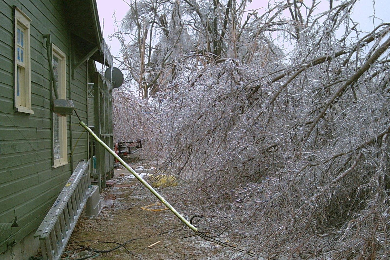
Electrical Rough In work can bring you to a hillside cabin in the woods…
…or to an expensive mansion with 24 foot ceilings. 

The Residential Electrical “Rough In” Step by Step

The Rough In Stage has 8 Steps;
    1) Layout the PlanElectrical locations are marked on the studs and floors.
    2) Acquire Material; Material is purchased or delivered.
    3) Nail up Boxes;  Boxes and can lights are mounted in exact positions.
    4) Drill the Framing;  Holes are drilled in studs between the boxes.
    5) Pull Wire;  Specific wire is installed from box to box, through the holes.
    6) Make up Connections; Wires are striped, stuffed into the boxes and connect together.
    7) Service Equipment; Mounting and making up the electrical panels, meter box, grounding, overhead or underground conduits and service wire.
   8) Inspection;  Check your work to see what was missed or messed up and then  arrange for a government inspection.
 
Residential Electricity 101  
  It is best to complete each step, in the entire house, before moving on to the next step except on a large house where it might be better to follow these steps on one portion of the house at a time.  For example you might start on the second floor to layout the plans and then nail up all the boxes, then drill the holes, pull all the wire, make up the connections and check your work before moving down to the main level to start the process all over again; layout the plans, nail up boxes … etc. Step 2, Acquiring Material, should be done after the Layout because the Layout of the electrical plans is where you learn all the materials that will be required to complete the job.  Most electricians will show up at the job with a truck load of standard materials that they know they will be used, and then after the Layout they will order the remaining missing materials.
  Step 7 , mounting the Service Equipment, can be started sooner while others are pulling wire.
  
Here is each step of the “Rough In” in more detail;

Rough In Step 1 Layout the Plan

 The location of electrical outlets is marked by transferring the electrical plans from the blue prints to the wall studs and floor.
 
 Introduction
  The first step of wiring a house is to layout the locations of all the electrical items.
A unique electrical shorthand or script,  is used to identify the placement of items.
Items like switches and lights, ovens and dishwashers. For example the letter “R” is written on a stud to identify where a receptacle will be located and the letter “S” is marked where a switch will go. Not all electricians use the same script, there is no standard. It is different from company to company, state to state and country to country. One Sparky (a common nickname for all electricians) writes “S3 Kit” for a kitchen 3 way switch, another Sparky writes “K3” with the “K” representing kitchen and the “3” for a 3 way switch. Same meaning, different script. Electrical script is written right on the wall studs and unfinished floors with a permanent marker or a heavy duty construction crayon. The idea is to transfer the electrical plan from concept to concrete, from an abstract idea directly onto the physical concrete, from the blueprint plan to the structure. When the layout is complete it looks like technical graffiti written all around the house. Electrical script will contain words, numbers, abbreviations and symbols.
   Here is some script that might be used;
HR = When you see this written on a stud it means a “home run” wire will be run from the panel to here.
S = This “S” written on a stud means a single pole switch will be located here.
S Van = This switch will be a single pole for the bathroom vanity light (the light above the mirror.)
S3 = A 3 way switch will be here.
PH = A phone plate will be here.
R = A single duplex receptacle will be here.
RR = A fourplex ( 2 x duplex receptacles) will be here.
© = This symbol written on the floor tells you a can light will go on the ceiling above here.
   Sometimes the customers add there own script in an effort to inform you of something that they want to add. They might have an after hours meeting with the builder and decide to add a receptacle high on the bedroom wall for a TV so they will pencil in “TV and PLUG “on the wall.
It is good to notice customers script. Go ahead and nail up the boxes for their additions but wait until you get verbal confirmation before you add any wiring. You need to make sure someone is going to pay for the additional wiring or the cost might come out of your paycheck.
 Residential Electricians consider several sources when determining electrical locations;
Government Electrical Codes
An Architect’s blueprints.
Instructions of the customer. 
Instructions of the builder.
Instructions of the Electrician’s boss or company policy. 
The Electricians Experience.  
  Government Electrical Codes. The National Electric Code and local government regulations will require specific locations on items in order to pass an electrical inspection. These codes might require an item like a smoke detector, to be placed in a specific location even if its not shown on the blue prints and the customer doesn’t want it.
  An Architect’s Electrical blue prints. A drawing, on paper, showing the locations of walls, doors, lights, switches and so on, as viewed from above, looking down. The services of an Architect are expensive and more likely to be used on commercial construction or a large, expensive mansion. 
Work on a small house usually has no prints at all. Some builders will provide mail order drawings or a drawing they made themselves. Unfortunately, these “do-it-yourself” prints soon become worthless as changes and additions are made to the structure. An experienced electrician will quickly determine if the prints are to be taken seriously, marking the script exactly as indicated.  Or if the prints are more of a general guideline or if they are totally useless.  
  Instructions of the customer. Sometimes the person buying the home will insist on placing an electrical item in a strange location that the builder would rather not do. If it is allowed by the code the customer will usually win since they will be the one paying the final bill.
  Instructions of the builder. A residential builder or General Contractor who builds several houses with the same layout might want certain items in exact positions. They might want a kitchen sink can light centered over the sink even if this requires reframing the ceiling joists.
  Instructions of the Electrician’s boss or company policy. It might be the standard policy of your company to have one switch for 2 attic lights even if the plans call for one pull chain light.
  The Electricians Experience. Or instinct. You mark a switch box next to a door. The code approves it, its on the prints, the customer and the builder want it but a problem occurs. Special, extra wide wood trim is ordered and nailed around the door. The trim is so wide it covers half of your switch box. Experiencing this problem or learning about it from a source like this, will teach you to mark and mount the box on a stud more distant from the door or to note that a small piece of 2×4 needs to be added to space the box out away from the door.
 
Measure, Mark, Move on.
   The Electrician in charge of the Layout will often times mark the script while walking through the house with the owners and/or builder. They will begin by finding a starting point in a room to mark their first item. Say, for example, the first item they come to is a bedroom switch. They will determine where the switches will be located based on which way the door will swing and the number of switches by looking at the blue prints or by instructions of the customer.  Then, at the stud next to the bedroom door, they will take their tape measure and mark the height where the switch box will be nailed in place. A good height for switches is 44 inches to the bottom of the box. Next, they will write the letter S near the height mark. This S represents a switch for the bedroom lights. Now, any electrician who enters this room will know that there will be one switch next to the door for the bedroom lighting. After identifying the switch location, they will move along the wall and write the letter R on a 2×4 wall stud close to where the first receptacle will be. No height is marked for general receptacles. The height can be set by holding the box on top of a standing hammer. They will continue to work their way around the room identifying every spot where a wall receptacle, phone jack or cable TV box will be located. Next they will draw a © (6 inch circle with a C in the center) on the floor below where a recessed can light will be mounted. In this example the bedroom will have 4 recessed can lights, 1 near each corner of the room. The electrician will draw all 4 can symbols on the floor, 1 at each corner. The electrical layout of this bedroom is now complete. An electrician who enters this bedroom can read the wall and floor script and determine where everything goes. They can see where to nail up the boxes for the phone, TV receptacles and light switch and that there is 1 switch for 4 can lights. Because no switch or light  is marked at the shallow bedroom closet they will know that there is no plans for a closet light. This process of measuring, marking and drawing continues in other rooms and areas until the Layout for the whole house is complete.
 
Succeed with Speed.
  Construction workers are expected to work quickly at all of their tasks. In the layout, it is faster to write the letter “R” on a wall stud, than it is to write “Nail up a single gang box for one receptacle here” It’s 5 times faster to write “R” than to write “Recep”  Writing nothing at all is even faster but only if everything can be nailed up without missing anything. Time will be lost if a receptacle is forgotten and you have to add it after sheet rock is installed. Some houses have a small and simple electrical layout. On these jobs the electricians might mark only switch heights and appliance locations to save time. Especially if the layout of electrical plans is identical to the last 10 houses the crew worked on. Instead of marking each receptacle they will lay the receptacle box on the floor directly below where it is to be mounted as they distribute the boxes around the rooms. Recessed can lights, fixture boxes and other ceiling items are also placed on the floor below the spot where they are to be mounted. Marking the locations of each and every electrical item becomes more important on larger, more complicated houses. 
 The key to properly marking an electrical layout is to provide plenty of information with a few simple letters and symbols.
 
 Marking the Layout requires experience.
  Beginner Electricians are not expected to perform the electrical layout but they are expected to learn the script and find all the marks. Be observant, look around. Some items, like a kitchen microwave, are marked high on the wall. Others marks on the floor might be hidden under construction debris.
   Marking switches on the wrong side of the door or forgetting to mark something like a garage freezer can be an expensive mistake to fix after sheet rock is installed. Because of this, marking the layout is usually done by the electrician most experienced in residential construction. This electrician is often assigned as the supervisor of the project.  In a large complicated mansion, this project supervisor will mark the layout days before any other electricians arrive.  Residential electricity uses different materials, methods and codes than commercial construction. Determining where to mark the locations of electrical items can be difficult for an experienced commercial electrician with little residential experience.  It is common for a 6 year residential electrician to be a project supervisor over a 10 year commercial electrician when working on a house.
  The job foreman or supervisor will have information about the house that you and the home owner might not know about. If the owner of the house comes up to you and tells you to add another light in a hallway, the two of you may not realize that a return air duct will be in that location.
  Any changes to the location of items should be brought to the attention of your electrical supervisor.
 
 
The Rough In
   Layout the Plan
>Acquire Material
   Nail up Boxes
   Drill the Framing
   Pull Wire
   Make up Connections
   Service Equipment
   Inspection 

Rough In Step 2 Acquire Material

Ordering, buying or unloading supplies.
     Material arrives at the jobsite in several different ways depending on the policy of your company;
    -All supplies are in the shop. You load them into your truck and head to the jobsite. 
    -Your company or you call in an order to an electrical supply store and have them deliver the 
      supplies to your jobsite. 
    -Your company or you call in an order to an electrical supply store and have the order ready for
      you when you arrive. 
    -You drive to an electrical supply store and purchase what you need on a company charge
      account. 
   To most Electricians this “Step 2 Acquire Material”  means; Start the day by loading the truck with basic supplies that are stored at the shop and then head to the jobsite. They keep a list of missing items as they work and load those supplies at the beginning of the next day.
   To an electrician who is new at wiring a house, it is best to complete the “Layout” Step first to get a good idea of how much supplies to purchase and learn of any special items that may need to be ordered. Rarely are beginners allowed to purchase supplies. Some companies don’t even let the experienced electricians buy supplies but instead have an office worker do all the purchasing. Still, you should learn the location of all your company’s electrical suppliers and their phone numbers.
If you are allowed to make purchases, establish good relationships with the sales staff, they can provide good insight into the latest code compliance methods and products.
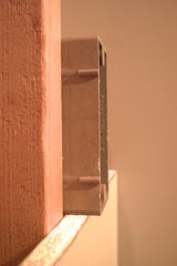
   Learn the proper names and slang names of electrical supplies. There is a big difference between a 1 gang single receptacle plate and a 1 gang duplex receptacle plate. A “retrofit box”, an outlet box that is cut into the sheet rock instead of nailed to a stud, is also known as a “cut in” box or an “old work” box or a “remodel box”  Some retrofit boxes require 2 box support straps also called; “F” straps or “Battleships”  because they look like these. The more terms and slangs you know, the better you will be able to communicate or translate.
 
The Rough In
   Layout the Plan
   Acquire Material
>Nail up Boxes
   Drill the Framing
   Pull Wire
   Make up Connections
   Service Equipment
   Inspection 

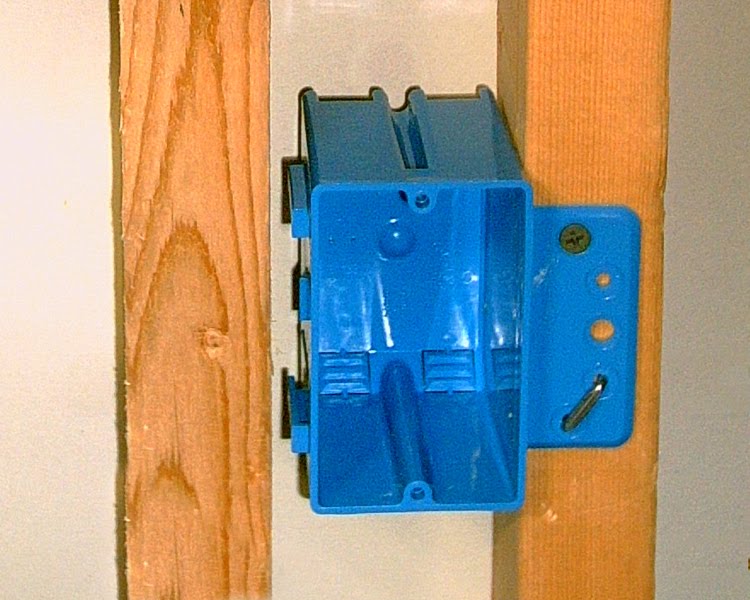
Rough In Step 3 Nail Up Boxes

Mount electrical boxes, housings and panels to the stud and joist framing before sheet rock is installed.
 
Using a hammer as a
measuring stick to set the 
height of a single gang,
nail on box for a receptacle. 
 After marking locations in the layout and acquiring your supplies the next step is to mount the electrical boxes and housings to the wall studs and ceiling joists. Mounting is done with nails, screws and staples. Nails come attached to most boxes and a few models of recessed can lights. Screws are enclosed with some items like ceiling fan boxes. Staples, that are used for wires, come in handy for mounting other items. Supplies are distributed around the house according to the script and then nailed in place.
  Most of the ‘Nailing Up’ step is simple enough to be done by an inexperienced electrician. Nailing up recessed can lights in the 4 corners of a rectangular shaped bedroom is real easy but nailing them up in odd shaped rooms or in ceilings with complex 45º joist framing can be more challenging.
 
    
First, Distribute the supplies.
   Electricians begin the Nailing up step by distributing supplies around the house. Someone will grab an armful of single gang nail on boxes and start laying them down on the floor, one at a time, under the marks that indicate where these single gangs will be nailed up. Someone else will distribute the 2 and 3 gang boxes. By reading the layout script, the electricians know which boxes go where.
     If the stud is marked “S” for switch, it will need a single gang nail on box for a single switch.
     If the mark reads SS it will need a 2 gang box for 2 switches.
     SSS needs a 3 gang. So does S1S3S4 , where there will also be 3 switches; one single pole (S1), one three way (S3) and one four way switch (S4)
     In cold northern climates, special boxes are used for insulated walls and ceilings. These boxes have an additional weather gasket attached to them. So an “R” on a wall between bedrooms would get a standard one gang nail on box but an “R” on a the bedroom wall that is shared with the outside will get a special one gang nail on box with the insulating gasket. A standard 4/0 light box is used when the space above the light is a second floor room but a special 4/0 box with a gasket when the space above is an insulated attic. 
     If the work area is somewhat clean then items for the ceiling can be set on the floor below their mounting location. If the area is cluttered and busy, set ceiling items by the wall switch that will control them. Single gang nail on boxes come in different depths. Your company might use 20 cubic inch boxes for all single gang needs. Other companies might use a deep 22 cubic inch single gang for GFI receptacle  locations. There is not much visible difference between a 20 and 22 cubic inch box. They should have the size labeled on or inside the box. You will be creating problems if you take this special deep box and nail it up in a place where it is not needed. 
   Recessed can lights are usually sold 6 to a case. These cases are distributed around the house to rooms where they will be needed. If a room needs 6 recessed can lights, then a case can be set by the switch box in that room. Can lights that are not in a case need to be set close to walls where workers won’t trip over them or have them tangle up in their extension cords. Some houses have only one style of can light housing. This makes it easy because everywhere the script locates a can it will be the same style. Other houses have a variety housing sizes and styles. You will have to know how the script identifies different styles of recessed can lights.
     Distributing light boxes is more difficult than the rest. Light boxes require knowing where center will be before you can decide which style of box to use.
     If the center is exactly on a ceiling joist then a pancake box is used.
     If the center is 2 inches off the joist a 4/0 nail on box is used.
     If the center is beyond 2 inches from the joist a bar hanger box is used.
Heavy lights in dining rooms and entryways require a heavy duty metal light box.
Ceiling fans require a special fan rated box.
 
The Nailing up begins after a good amount of boxes and can lights are distributed around the house.
   The basics of nailing up any “nail on” box;
   Know the height method and measurement. Know the depth of the finished wall or ceiling. 
Nail the box level, flush and plumb. Boxes that are very close together need to be nailed up at more exact heights.   
Know the height method and measurement.
   Electricians  use different height methods for mounting device (switch and receptacle) boxes. Be sure to use the same method as those you are working with. Some measure, mark and nail the box with the mark even with the bottom of the box, others set the mark even with the top of the box and yet others nail the box with the mark in the center.  It is best to mount rectangular device boxes with the mark on the bottom of the box and round boxes with the mark at the center of the box. Use 44″ to the bottom of switches, kitchen counter outlets and garages. But, follow your companies methods.
Know the depth of the finished wall or ceiling. 
   You want the box to be flush, not sticking out past the sheet rocked wall surface and you also don’t want the box sunk deep into a wall. 90 % of houses  use 1/2 inch sheet rock which means your box can stick out according to the depth marks indicated on the side of your box. Fire walls, between a duplex or other apartments, might have a double layer of 1/2 or 5/8 inch sheet rock. Sometimes, 1″ thick brick is used on the inside walls. Check the prints or ask your supervisor for the correct depth.
Nail the box level, flush and plumb. 
   A 4 gang switch box looks pretty bad when it is not level. Loosen or sink one of the 2 nails until the box is level. A properly nailed box can still stick out of the wall on one side if the stud is twisted. Try hitting the stud at the bottom until your box looks flush (it will not stick out when sheet rock is installed) A plastic switch box can twist and distort. The top and bottom can be level but, because of a twist in the middle, the top screw hole will be out of plumb with the bottom screw hole making it hard to mount the device. Loosen or sink one of the 2 nails until the box screw holes are plumb. 
Close boxes have to be more exact.
   Take a little more time to get the exact height when 2 separate boxes are on either side of the same stud at the same heights. Especially on a kitchen counter.
 
   The basics of nailing up any recessed can light;
   Find the center mark. Orient the j-box. Mount to one joist at a time.  Lock into exact position.
Find the center mark.  
   Measure off the wall, that the ceiling joists are heading to, and mark your center on the ceiling joist with a marker. On complex ceiling framing, attach a string to the ceiling, parallel with the wall, to help you find your centers.
Orient the junction box
   Recessed can lights come with an attached wiring compartment or junction box. Think about the best placement of the junction box before mounting a can light. If you know your wires are coming from the right then spin the can light around until the junction box is facing the right.
Mount to one joist at a time 
   Place the can on the center mark and grab the can and the joist with one hand while nailing the 2 brackets with your other hand. Then slide the brackets over to the other joist and nail in place.
Lock into exact position
   The can should be able to slide on the brackets from one joist to the other. Measure off the other wall and mark your center on your brackets. Slide the can until it is centered on your mark and lock the can into position. Can lights are locked into position by tightening a bracket screw or by using your lineman pliers to fold a piece of metal that the bracket passes thru.
  
The Rough In
   Layout the Plan
   Acquire Material
   Nail up Boxes
>Drill the Framing
   Pull Wire
   Make up Connections
   Service Equipment
   Inspection 

Rough In Step 4 Drill the Framing

Creating a pathway, through the framing, for all the wiring throughout the house.
Milwaukee’s “D” Handled Drill
Milwaukee’s “Pistol Drill
Introduction to Drilling
   You are ready to begin drilling when the electricalLayout is complete and all the boxes and housings have been Nailed up  according to your script markings on the walls and floor. Drilling too soon might cause you to waste time and energy drilling extra, unnecessary holes. With everything nailed in place you can see the box to box wiring path where your holes will need to be drilled
   The basic idea of the Drilling step is to provide a pathway for all the wiring that you will be running throughout the house.  Electrical wires, low voltage door bell wires and, when required, phone and TV wires. For example you will drill a line of holes along the length of a wall from receptacle box to receptacles box, and a hole above a switch box to run a cable up to a light. The goal is to drill as many holes as possible without drilling any unnecessary holes. When it is time to start pulling wire you want to be able to pull the wire through the holes from box to box without having to stop to drill a missed hole.
     The more holes (necessary holes) that are drilled before pulling wire, the less risk there is of accidentally drilling through a wire.  There might be 3 electricians pulling wire and only 1 company drill. If only ½ the holes are drilled throughout the house then 2 of these 3 workers will be waiting for the drill. They will have to stop pulling wire every time they discover another hole not drilled. All of this will slow down productivity. To avoid this delay someone has to drill and keep drilling until all the holes needed are drilled out.
  Some drilling requires more advanced knowledge of the jobsite’s circuit and wire pulling plan. If you know the circuit plan then you will know which way to drill; up, down, left or right. Other drilling pathways are more predictable.
 
     Here is a list of good places for a rookie to begin drilling because they are so common;
>The path connecting receptacles and switches in a bedrooms.
>Above a switch box
>Above a vanity receptacle.
>Above a phone or cable TV box
>Above garage receptacles and garage door eyes.
 
Safety;
     The drill’s side handle can spin around and hit you in the head, try to hold the drill at a distance or rest the handle against a stud. Drilling without the secondary, detachable side handle can injure your wrists. Long hair, coat hood strings or necklaces can get caught in the spinning drill bit and cause injury.  Wear safety glasses, drilling up and into an unseen nail can cause hot metal shavings to fall into your eyes. 
The rough in drill bit  
It is recommended that you use a ⅞ inch wide by 17 inch long bit with a double cutting edge. The bit needs to be long enough to drill through 6 to 8 framing studs that are nailed together.
 
   General drilling techniques;
Drilling across a wall
  Keep your holes in the center of the stud so that a sheet rock screw can’t damage the wire running through it.  The code requires a nail plate to be nail on the stud by your wire if the hole is too close to the nailing surface. Try to drill your holes level with each other, the same height off the floor. It doesn’t have to be exact, just somewhat level. Don’t drill so low that your holes will be at the height where the base trim will be nailed. Avoid the mounting screws of upper and lower kitchen cabinets by keeping your holes within the back splash area of the kitchen counter. 
   When you pull your wire around a bedroom, from receptacle to receptacle, the wire will go up the stud from the box to your hole, thru your holes and back down to the next box. If your holes are a foot higher than necessary, you will be wasting a foot of wire to get up to your hole and another foot wasted going back down. 2 feet of wasted wire between 2 boxes with 50 more boxes to wire; 2×50=100 feet of wire wasted. Keep your holes within 8 inches above or below a line of boxes to save wire and make you a more productive and valued employee.
Drill through the soft spots
  Avoid drilling through knots and nails. Knots are created from the branch of a tree and are common in framing lumber. They are made of very hard wood making it difficult to drill through. If you start a hole and you realize you are going real slow because of a knot, stop and start a new hole 2 or 3 inches away from the knot.
  Avoid nails that you see and areas where you know nails are, like where a stud is nailed to a bottom plate. When you hear or feel your bit hitting a nail, stop drilling and start a new hole or you can try to remove the nail and then continue drilling. Unfortunately there are times when you just have to go through no matter what happens.
Protect the drill bit tip
  Avoid hitting concrete or bricks with the tip of the drill bit. Sometimes brick or concrete lies just beyond a stud that you are drilling, especially in basements. Try to ease off on the drill so you don’t bounce into these hard surfaces. Concrete will damage the threaded tip on the drill bit. The threaded tip helps to pull the drill bit into the wood. When it is damaged you will have to push really hard. It is easy to sharpen the cutting edge of a drill bit but fixing damaged threads on the pointed tip is very difficult.
Look before you drill
   Look around to the back side of the wood before you drill through. You don’t want to damage a plumbing pipe or wires hiding on the other side of the stud or joist. If you damage a plumbing pipe, be sure to tell your boss or the plumber. Most repairs are easy and cheap to do before the sheet rock is installed. If you don’t tell someone, it might go unnoticed until the house is finished. Then when the water is turned on it will leak out and cause expensive damage.  
Drilling up
   Many wires are run up the wall, through the top plate and across the ceiling. For example a wall switch for a ceiling fan will have a wire run from the switch box up the wall and across the ceiling to the fan box. Holes need to be drilled through the top plate above switch box.  Electrical panels will have many wires, called home runs, that will have to pass through several holes in the top plate. If your company will be pulling the phone wire and TV coax cable, a hole will be drilled above and/or below each phone and TV box.
  When drilling up through the top plate the drill handle can spin around and hit you in the head, try to hold the drill at a distance or rest the handle against a stud.
> Start the bit very slowly into the wood to see how the handle will move as it spins clockwise.
> Allow the handle to slowly spin until it rests against a stud.
> Adjust your body and drill position to prepare for this spinning force and begin drilling.
Tall walls
  An average worker will be able to reach and drill the top plate on an average wall using the standard 20 inch electricians drill bit. Walls exceeding 10 feet will require the use of a small ladder.

Insert a 17 inch drill bit into this extension to drill
out the tops of tall walls without a ladder. Insert a
short bit to equal the more expensive 17 inch bit
and save money when the bit has to be replaced.
photo courtesy www.idealindustries.com 
The ladder will have to be carried around to all the locations that need a hole drilled up through the top plate.  Using a 20 inch extension bit will allow a greater reach and make drilling faster by avoiding the need to haul a ladder around.  The extension bit is inserted into the drill and the drill bit is inserted into the extension. 
Drilling down
   When drilling down, prepare to stop the moment you punch through so you don’t hit something like a pipe or vent. Some houses have floors heated with specialized plastic hot water pipes attached to the bottom of the floor. It is hard to avoid hitting floor pipes. Try to drill slower and with easy pressure the moment your bit is about to break through the wood. If you know that floor heating crew is about to begin, get all your floor holes drilled quickly.
   When drilling down it is common to end up stuck in a floor joist. You drill and drill and never seem to get through to the lower level because you are drilling through a 12 inch floor joist. When this happens, stop, pull the bit out and drill a new hole down at a double 45º angle. Meaning 45º off a plumb line and 45º off a north-south wall line (north-east is 45º from a north south line) If the wall is running north-south and the floor joists are running east-west, aim your drill bit at a 45º angle pointing northwest (or northeast, southwest etc..)  
Drilling out
   There are several wires that will have to extend to the exterior of the house. Outside wall lights, outside receptacles and air conditioner units are the most common places that holes will need to be drilled out. Sometimes the hole has to be in an exact location. For example, the hole for air conditioner wiring should be 2 feet directly above the unit’s condensation lines. A disconnect box will be mounted where the wire sticks out. If the hole is drilled to the side instead of directly above the condensation lines, the disconnect box might end up behind the unit making it hard to access.
When the exterior is going to be bricked, your holes drilled out don’t have to be in exact locations. There will be a space between the wall surface and the brick that allows your wire to reroute from the hole to the exact box location. 
 
 When most of the drilling is complete, you are ready to begin pulling wire. 
 
The Rough In
   Layout the Plan
   Acquire Material
   Nail up boxes
   Drill the Framing
>Pull Wire
   Make up Connections
   Service Equipment
   Inspection 

Rough In Step 5  Pull Wire

   Wiring together electrical items in separate groups or circuits and connecting them to the panel. Pulling phone, TV and low voltage wiring like garage door openers, doorbells and thermostats.
Introduction to Pulling Wire;
   Let’s review what we have learned so far;
>First we had to Layout The Plans. We marked the wall studs and floors to identify the locations of electrical items.
>Then we went shopping for material.  Or, we arrived before the Layout with a truck load of material ready to get us started and we will acquire more material when our supplies run low
>Next we Nailed Up Boxes. We nailed up boxes, exhaust fan housings, stair light housings and recessed can lights in the locations identified in the Layout.
>Then we Drilled the Framing. We drilled holes for our wires in the wall studs, joists, top plates and bottom plates.
 
  Now we are ready to install the wiring. To an experienced electrician, pulling wire is as simple as driving a car. To a beginner, both driving a car and pulling wire can be incredibly confusing. Wires spreading out in all different directions appear to be a complex, tangled up maze. Yet they are a well organized collection of individual circuits. Each circuit a miniature highway created for microscopic electrons to travel on. Bumper to bumper they move from the transformer at the street through meter, through the circuit breaker in the panel, through a switch, through a light bulb and back again to the transformer.
 Someone once described pulling wire as “Connecting Dot to Dot”  from point A to point B or from box to box to box to the panel. Any boxes not connected to the panel or to another box that is connected to the panel, will not have any power and will not work. This group of boxes connected together including one wire heading to the panel is called a circuit. The wire heading to the panel is called a “Home Run” Beginners should work on one circuit at a time pulling the Home Run first and then interconnecting all the boxes on that circuit. A wire is pulled from the first box, with the Home Run, to the 2nd box and stapled to the stud by the 2nd box. The wire is cut and then stapled at the first box. Next, the wire is pulled from the 2nd box to the 3rd box and so on.  (The code requires the wire (NMB 14/2, 12/2 …) to be stapled less than 12 inches away from boxes and every 4 feet 6 inches with no more than 2 wires under each staple and stay an inch and a quarter away from the nailing edge of the stud.) The wire is left outside the box, unstripped. Stripping off the sheathing and stuffing the wires into the box is done in the “Make Up Connections Step” after all the wire pulling is complete.
Residential Electricity 101 Wire Pulling guidelines;
>Eye hazard. Hold the end of the wire to prevent it from whipping back into your eye.
>Wires come in different sizes The most used is size 14 and size 12. Make sure you are using the correct size wire for your circuit. Find the size by reading the label on the sheathing or use the wire gauge on your wire stripper.
>Wires come in different types 14/2 and 14/3 are both size 14 wire but one has 2 conductors and the other has 3. Make sure you are using the correct type of wire.   Find the type by reading the label on the sheathing or stripping off the sheathing and counting the number of conductors inside.
>Some wires have to be identified or labeled by you  Before an electrician can make up the wiring connections at a switch box they have to know which wire goes up to the light because that is the only wire they want the switch to shut off. This wire (NMB cable with a black wire a white wire and a bare ground) is called a switch leg and one way to find it is to get up on your ladder and use your hands to follow the wire from the light down to the switch box being sure not to confuse it with the other wires stapled along side of it. An easier way to find a switch leg is to label it when it is pulled from the light to the switch box. Switch legs are not the only wires that need to be identified.  
   The 4 most common are;
1) The Switch Leg  2) The Home Run  3) Travelers  4) GFI’s Line and/or Load
   There are different methods to labeling wires and not all electricians agree on which method is the best. The 3 most common ways to label wires during residential wire pulling are; marking, folding or crimp scoring.
Marking; The best method for beginners and complex wiring. A permanent ink marker is used to write information directly on the sheathing near the end of the wire.  Write “HR” to label a wire as a “Home Runs” (the wire that runs to the panel), “Cans” for a switch leg to the can lights,  “Fan” for a switch leg to a fan, “Line” “Load” for GFI’s, “Trav” for travelers.
Folding; The best method for simple wiring. The end of the wire is folded in different ways for different meanings. 1 fold like a J means switch leg or at a GFI the switched off load side, a curl like curly fries means Home Run, 2 wire travelers are twisted like licorice, 3 wire travelers are wrapped around the switch leg.
Crimp Scoring; Worst method that should be banned. A lineman pliers or a wire cutter is used to slightly cut into the cable sheathing and wire insulation, leaving a score mark on on both.Different score marks have different meaning. Usually 1 score means a switch leg or load, 2 scores a Home Run and an X score means travelers.
   The problem with crimp scoring is when it cuts into the copper conductor creating a dangerous nick. Everything is fine if the nicked wire is thrown away but there is a risk that the nicked conductor will be used in the box. Nicks reduce the size and ampacity of a wire and promote arching or sparking. Nicks become weaker when folded back and forth. If a nicked wire is used as a pigtail, it will become weaker when folded into the box and often times break the connection. If you have a choice, do not crimp score wires.
 
Wires have to be secured and supported according to specific  rules.
   The wire has to be stapled at specific intervals with limits on how many wires can be under one staple and within a close distance  from the box or light.
There are limits to how many wires can be inside one box 
   The cubic inch volume is marked on the inside of a nail on box. The NEC explains how to calculate how many wires you can stuff into your box based on its volume and the size of your wires.
There are things wires should stay  away from;
– The sharp edges of metal found on; air ducts, plumbing straps and metal truss framing couplers and framing brackets.
 – Heat; Do not lay your cable on or near hot stuff like metal chimneys, hot water pipes or the top of a recessed can lights .
 – The area where crawl space vents are cut in which is above the concrete foundation in the outer floor joist.
 – Below bottom plates and on top of top plates where drill bits will venture.
There are spaces in the framing of a house where wires are not allowed.  
   An empty wall space during the Rough In Stage can be completely filled from stud to stud with a built in wall iron allowing no room for you wire to pass thru. Be careful not to pull wire thru areas designated for built in iron boards, skylights, attic  fans, attic access holes, garage attic  pull down stairs, pocket doors,  return air vents or recessed medicine cabinets.
Avoid Rope burn
   Rope burn, a fast moving wire rubbing againest a stationary wire, will take the insulation off of a wire. Avoid pulling wires in such a way that one fast moving wire rubs against another especially through holes in the framing.
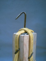
Make a wire reel

   A wire reel will help unroll your wire as you work. Use 3 wire reels to pull 3 home runs at the same time. A wire reel can be built from materials found on the job. See diagram below; 
How to make a “Wire Reel”  (“Wire Spinner” or “Wire Tree”) Nail together 3 2×2 ‘s or 2×4 ‘s about 30 inches long and staple on 2 runs of 14/2 or 12/2 as shown. At the top is a nail thru a washer then thru both
 runs of 14/2 which are stapled as shown to hold the nail in place. Bend the nail so you can hang it 
from a staple on a ceiling joist.
A close up view of bent nail set through a washer and 
2 runs of 12/2 wire. The head of the nail will spin on
the washer as the wire spins off the reel. For a closer
 view click on the photo. Free free to copy and share.
    Drive a staple into the side of a ceiling joist. 
  Hang the wire reel by hooking the bent nail
            through the staple. Now the wire will 
spin off easily.
 
The wire pulling step consists of 5 different tasks;
Creating the circuit plan, pulling circuits, pulling low voltage wiring, pulling Home Runs and pulling TV coax cable and phone wire.
  1) Creating the Circuit Plan.  A very difficult task.
Only an architect or a licensed electrician will create the circuiting plan by following all the rules established in the National Electrical Code, state and local codes, builders requirements and your own companies policies.
  2) Pulling circuits.  A hard task to learn.
It involves connecting together all the boxes and electrical items that will be on one circuit breaker. It consists of many short lengths of wire run from box to box and might also have different types of wire (14/2, 14/3) 
A roll of wire is set up on a wire reel. Take a visual preview of all the boxes that will be on the circuit and then begin pulling the wire thru the holes in the wall studs from the first receptacle box to the second recep box and cut the wire. Staple the wire by the boxes and repeat this process by pulling another wire from the second box to the third receptacle. The hard part is knowing which light boxes will connect together and to which switches they will be controlled by. 
  3) Pulling low voltage wiring. Moderately easy.
It includes small wiring for thermostats, door chimes and such.  A thermostat can be a simple as pulling an 18/5 wire from a hallway stat location to the furnace unit. A door chime uses 18/2 from the front door to the hallway chime with the chime’s transformer located in a 2 gang box behind the chime.
  4) Pulling Home Runs. An easy task to learn. 
A home run is a wire pulled from a circuit to the circuit breaker in the panel. It is the longest length of wire on a circuit.  A roll of wire is set up on a wire tree (see photo above) near the circuit like a  bedroom.  The name of the circuit is written on the end of the wire “Master Bed” The wire is then carried up into the attic (or by some other route) and then walked across the ceiling to the area above the panel where it is brought down. Then the home run wire is stapled to the studs and joists all the way back to the closest box on the master bedroom  circuit. After a little practice pulling one Home Run at a time, try pulling 2 Home Runs at the same time. This will make you twice as productive. Eventually you should be able to pull 4 Home Runs at the same time. Pull all 4 Home Runs across the attic to the panel and then staple your way back.
  5) Pulling TV coax cable and phone wire.  Another easy task to learn.
A box of phone wire or coax cable is set up near the electrical meter or at a media distribution panel. The wire is then pulled up into the attic (or by some other route) and then walked across the ceiling and brought down to a box where a phone or TV will be located.  Then the wire is stapled to the studs and joists all the way back to the starting point 
 
 Although the tasks of pulling home runs, TV coax and phone are the easiest to learn, they can be physically difficult. Like pulling a home run from the panel in the basement to the bedroom up on the second floor. No complex calculations just get the wire from ‘way down there’ to ‘way up there’.
Pulling a circuit requires more knowledge. As a beginner you will most likely be assigned the simple but more physical tasks until you are ready to learn the circuits.
  Before the wire pulling begins, everyone gathers together to hear the game plan to determine;
         Which task each electrician will be assigned
          How the circuits will be arranged.
          Notice is given to avoid areas of the house that are unfinished or changing. 
Beginning with a game plan helps to avoid confusion. Each electrician is assigned different tasks and different areas of the house to work on. Productivity can be wasted if 2 electricians unknowingly work on the same task. A skylight might have to be cut into the ceiling framing. Knowing this before you begin will save you allot of rerouting.
 
A wire pulling example;
  OK so lets begin to pull wire; the circuit plan has been established by your supervisor who has assigned you to pull a 15 amp “Bed + Bath” circuit with size 14 gauge wire. You are told this will include all the lights, receptacles and fans in the guest bedroom, the closet and the hall bath.
But not the vanity counter receptacles nor the hot tub. The holes for your wire have already been drilled out.  Grab a roll of 14/2 wire and set it up on your wire reel. 
  Begin your circuit by pulling the home run to the panel. In order for your “Bed Bath” circuit to work, you have to “Feed” it power from the electrical panel. The wire that feeds power from the panel to a circuit is commonly call the “Home Run” Label the circuit on the end of the home run wire with a marker write “Guest bed + hall bath”  Throw the wire up thru the ceiling framing into the attic. Climb up your ladder into the attic and walk the wire across the ceiling over to the panel location. Let the end of the home run hang down near the panel with enough length to eventually go thru the holes above the panel , down the wall past the panel and touch the floor. Now staple your home run about every 10 feet all the way back to the guest bedroom. Be sure you have enough wire to reach the switch box and then cut the wire. Next, send the end of the wire thru the hole in the top plate straight down the wall stud to the switch box and staple in place. Now mark this end of the wire as the “home run” so that everyone knows where it is and that it has been pulled. By labeling the home run at both ends, you can be absent tomorrow and another electrician can finish your circuit knowing that you already pulled the all important home run.
Circuit Status; Home run pulled to circuit
  Now that we have fed power to the circuit with the “Home Run” we have to “feed” the power around the walls to all the switches and receptacles (not lights or fans). Take a moment to look at all the switch and receptacle boxes on your circuit and determine the shortest path to run your wire. Make sure you run your wire to the boxes facing into your rooms not those boxes facing away from you into another room like the living room. Remember we are connecting together switches and receptacles but not the lights. We’ll get to the lights later.
  OK now connect the dots. Start at the switch box where we left off with the home run. Run your 14/2 wire thru the wall studs to the nearest receptacle with enough length to reach the box and go another 12 inches. Staple your wire in the center off the stud and within 8 inches of the box. Now staple the wire again at the switch box where you started. Before cutting the wire, make sure it will reach the box and have another 12 inches. When you have enough, cut the wire. 
Circuit Status; Home run pulled to circuit at bed switch with feed pulled from switch box to first outlet.
  Now you have a home run feeding the circuit from the panel to the switch box and a feeder wire from the switch box to the first receptacle box. Now just continue connecting box to box skipping over those boxes that belong to and are facing other rooms that are on your wall studs but not on your Guest Bed + Hall Bath circuit. Also ignore the 2 receptacles on your hall bath vanity counter and the hot tub.
  Feed the next receptacle facing in your room. Run your 14/2 wire thru the wall studs from your first recep. to the next recep. Staple in the center of the stud where sheet rock screws can’t reach and, again, leave enough length at the box, at least 12 inches. “Better too much wire than too short.”
Circuit Status; Home run pulled to bed switch with feed pulled from the switch box to the first outlet and another feed pulled from the first outlet to the second outlet.
  Because of doors and other obstacles, not all the runs will be as simple as going thru a couple of wall studs. The next box to feed is the closet switch box but it is on the other side of the closet door. The wire will have to go up into the attic, over the door and back down the wall to the closet switch box. Grab your ladder and wire and run the wire down thru the hole above the recep box. While up on your ladder, staple the wire at the top of the stud and across the attic. Get down from your ladder to staple half way down the stud and again near the box. Move your ladder near the closet switch box. Pull enough wire to reach the switch and cut the wire. Go up the ladder and run the wire down thru the hole above the switch and staple.
Status; Home run pulled to bed switch with feed pulled to first and second receptacles and to the closet switch.
 Below the closet switch box is a receptacle box.  Staple a wire at the bottom of the closet switch box and again at the recep box and cut the wire.  Except for this last box, all the boxes that we have pulled wire to have only 2 wires at them. It is permitted to pull a 3rd wire to a box and we need a 3rd wire at the closet switch box to control the closet light. This wire going from the switch to the light is called a “switch leg”  The “switch leg” will only be hot when the switch is on allowing current to flow thru it.  This is different from all the other “feed” or “hot” wires we pulled so far in this example. Feed wires are hot whenever the circuit breaker is turned on. (assuming that you connected them all together)Because the “switch leg” is different it has to be identified so you will know which wire to put on the switch. If the Switch Leg wire (black wire only) is not put on the switch you will not be able to turn the light off.  As a beginner, always identify your switch legs with a marker by writing the name of what the switch leg is switching. In this example, write “Closet Light” on the sheathing near the end of the wire. Do this in addition to your companies policy of labeling by folding or labeling by crimp scoring.
  
The Rough In
   Layout the Plan
   Acquire Material
   Nail up boxes
   Drill the Framing
   Pull Wire
>Make up Connections
   Service Equipment
   Inspection 

Rough In Step 6 Make up Connections

   When all the wire pulling is complete, it is time to begin making up the wiring connections.
The ends of the wires that are stapled outside of the box, are stripped from their sheathing and placed inside the box and then about a 1/2 inch of insulation is stripped off of each conductor. Specific wires are twisted together with a lineman pliers, capped by twisting on wire nuts and folded deep into the box where the sheet rocker’s tools will not damage the conductors insulation. 
   Take notice of the key points and recommended methods mentioned here;
             1) All the wires are pulled and left outside the box until all wire pulling is complete. 
             2) The sheathing (not wires) is stripped outside the box and then inserted into the box.
             3) The stripped ends of the wires are twisted together with a lineman and then capped.
   These methods are not followed by all Residential Electricians. Some place the wires into the box as soon as they pull it to the box. This is not recommended. The wire pulling will go faster if you don’t stop to strip and stuff each wire. Also, waiting to strip wires when all the wire pulling is complete will make changes easier. Pull all wires to the box and leave them unstripped outside the box until it is time to make up the connections. 
    Others strip off the sheathing after the wire is in the box. This too is not recommended. Stripping the sheathing inside a box can cause a nick in the metal conductor that is difficult to noticed. A nick in a  metal conductor reduces the size and ampacity of the wire and can promote sparking. When working on connections or installing switches, the wires get moved around alot. This motion can cause a nicked wire to break off. Strip the sheathing outside the box where you can inspect the insulation on each conductor before inserting the wire into the box.
    Other Electricians will hold the ends of stripped wires together and twist on the wire nut without twisting the wires together with a lineman pliers first. This is not recommended because some of the wires might pull loose from the connection causing sparking or lost power. First twist the stripped ends of the wires together with a lineman and then twist on the wire nut
Stripping off the sheathing
   First we have to remove the correct amount of sheathing. The sheathing has to extend into the box 1 inch. Hold the cable next to the box and find the point on the cable that would extend 1 inch into the box. Score the sheathing at this point. The sheathing can be scored with a knife or with the teeth of your stripper. Pull the sheathing off the wires and insert the wires into the box.   
Stripping UF sheathing
   UF or “underground feeder” can be buried in the ground. It is different from standard wire. Instead of wrapping the conductors in a sheathing they are totally encased in solid plastic making they difficult to separate and strip. To separate the wires, grab the center, bare ground and peel it back out of the plastic. This will expose the black and white wires which can also be peeled out. Cut off the excess plastic. 
Stripping off the insulation
  Some use a lineman pliers to strip the insulation off a conductor. They pinch the wire with the cutting blade to score the insulation, then pivot the pliers back and forth to score all around the wire and then slide the insulation off the end if the conductor. This method is OK if you can do it without nicking the metal conductor.
  The best way to strip off the insulation is to use a wire stripper. The stripper has different sized grooves for different sized conductors. Some wire strippers are for solid wires, others are for stranded wires. If you are using size 14 wire, set the wire in the groove labeled 14 and close the stripper. This will cut the insulation without nicking the metal.  With the stripper held closed, slide the insulation off the end of the wire.
   Connecting the wires;   When connecting wires it is best to twist the conductors together with a “lineman’s pliers” before screwing on the wire nut. Hold the conductors so that the ends of their insulation are even (rather than the ends of the copper) Grab the ends of the wire with your lineman and twist several times (about 360 degrees twice) Cut off the end of the finished twist of copper that exceeds 1/2 inch. Screw on your wire nut. If you can see the copper part of the wires sticking out of the wire nut then remove the nut and cut off more of the copper.
   Combining solid wires with stranded;
When combining solid wire with stranded wire, always hold the stranded slightly longer than the solid, about 1/8 inch past the end of the solid, to ensure that the wire nut grabs the stranded as you screw it on.  If you have multiple wires, twist the solid wires together first then twist the stranded wires together, then hold the stranded wires 1/8th inch past the solids and screw on the wire nut.
   Different size wire nuts;   Wire nuts come in different sizes and colors. Each size has a limited number of wires that it is designed to connect. The number of wires permitted is printed on the packaging the the nuts are shipped in.
   Packing the wires into the box;   Try to fold the wires into the box neatly, keeping the wire ends towards the front of the box where they can be easily pulled and attached to the devices.
 

Rough In Step 7 Service Equipment

 Mounting and making up the electrical panels, meter box, grounding, overhead or underground conduits and service wire. 
Service equipment includes; panels, ground rods, meter box, main disconnects, service conductors and the over head or underground conduit. The construction of the service equipment is normally done by a more experienced electrician and not by a beginner. 
  It is important for a beginner to know how many panels there are, where they are located which circuits belong in each panel and that your Home Run is long enough to reach the bottom breaker.  A large mansion can have a 40 space panel in the basement, another one upstairs and a third in the garage. Before you pull your home run you will need to know which panel you are heading to. The electrician in charge will divide the circuits between panels in a way that will balance the total electrical load evenly. 
The Rough In
   Layout the Plan
   Acquire Material
   Nail up boxes
   Drill the Framing
   Pull Wire
   Make up Connections
   Service Equipment
>Inspection 

Rough In Step 8 Inspection

Inspect your work for errors, missing or unfinished work. Call to arrange for a government inspection.
   Experienced electricians are constantly observing the quality of their own work and the work of their company. Even as they walk to lunch they might observe the jobsite wiring looking for something missing or out of place.
   Beginner electricians are more concerned about what they are going to do after work. Beginners have trouble recognizing that they did not finish their assignment. Finished means 100% complete not 90%  Beginners will say “I’m finished” yet when you check their work 5 to 10% of their task is incomplete, not because they didn’t know how to do it, but because they just didn’t do it and they didn’t check to see if they missed anything.
Check your own work;
               1) Verify that the Home Run (wire to panel) is connected to your circuit.
               2) Visually follow the wiring around your circuit to ensure that all boxes are connected
                    together and that all wires are in the box.
               3) Consider the mistakes you, or others, have made in the past and check to see if you 
                    made them again.
               4) Check to see if any changes or additions were completed as instructed by the builder
                    or customer.
Check your teams work
Common mistakes
   1 of 3 wires not inserted into the box
   Closet light wire not inserted into box
   Wire to fireplace inserts forgotten or not connected
   Wrong depth on a  bar hanger style light box
   4 gang box not level or flush with sheet rock
   Forgot to set boxes on the wires for outside receptacles in brick
   Missed fire caulk or nail plate
Categories
Residential Electricity 102

Drilling Walls For Electrical Wiring

How to Drill Walls

As mentioned in Residential Electricity 101 the basic idea of the Drilling step of an Electrical Rough In, is to provide a pathway for all the wiring that you will be running throughout the house.
Not only electrical wires but also low voltage wiring for door bells, garage doors, phone and TV coax.
The key points we learned;
> Keep your holes in the center of the stud
> Drill as many holes as possible without drilling any unnecessary holes.

 > The more holes (necessary holes) that are drilled before pulling wire, the less risk there is of accidentally drilling through a wire.   
 > Keep your holes in the center of the stud
 > Try to drill your holes level with each other, the same height off the floor. It doesn’t have to be exact, just somewhat level.
 > Avoid the area where wood trim is nailed so the nails don’t hit your wiring;   Trim is nailed close to the floor and close to windows and doors.
 > Avoid the mounting screws of upper and lower kitchen cabinets by drilling your holes across the back splash area of the kitchen counter.
 > And in case you missed it,  Keep your holes in the center of the stud! 
   If you did miss it; that this was mentioned 2 times before, you need to pay closer attention. 
When electrical apprentices don’t absorb or clarify instructions they end up getting shocked or hurting someone else.  Pay attention, listen closely. To clarify instructions you can ask questions about the instructions or repeat the instructions back to your boss;  
   You ask,”OK So you want me to run a 14/2 home run from the panel up to the attic, across the attic and down to the hot tub, right?” 
    Boss, “Yes but use 12/2 not 14 and run it down to a GFI receptacle in the closet first, then to the hot tub.”
   You “Can’t you use a GFI breaker and run the 12/2 directly to the hot tub?
This nail plate is used to protect the wire
from screws and nails like those used to
attach sheet rock and wood trim.
Nail plates are attached to the stud where
the wire is too close to the surface. 

http://www.grainger.com
   Boss, ” GFI breakers cost $30 and GFI receptacles cost $10″   
 
   Knowing why something is done can help you remember to do it.  So why should we drill our holes in the center of the stud?  Because the closer the hole is to the nailing edge of the stud the greater the risk of a sheet rock screw or a trim nail penetrating your wire.  If there is a concrete basement wall one one side of your stud then you can drill your hole off center closer to the concrete where nails cannot enter the stud. The idea is not as much about “center” as it is to be as far away from nailing surface as possible. The code requires a nail plate to  be nailed on the stud by your wire if the hole is too close to the nailing surface. Nail plates are an extra cost taking extra time. Apprentices that use less material in less time and don’t fail an electrical inspection, are worth more dollars per hour. 
   There will be times when you cannot drill your holes in the center of the stud, when it happens use a nail plate to protect your wire.

Drill with a close angle


   Keep your drill close to the wall and pointing in the right direction.
Stay in the center of the stud and watch out for nails. If you hit a nail, pull the bit out and start a new hole nearby.


   This drill is pointing in the wrong direction. The angle off the wall is too large.  The holes in the 2nd, 3rd and 4th stud will not be in the center of the stud. This bit will not make it to the box but will end up out in the back yard.

Avoid “Built in” Ironing boards

   Because “built in” ironing boards (built into and flush with the wall) are not set in place during the electrical rough in, the wiring passing through the holes you drilled along the wall can interfere with the installation of the ironing unit. Check to see if the house will have a “built in” and mark the pocket location on the sole plate down at the floor. Any holes drilled at this pocket will need to be above or below the ironing board. 
   Notice in the photos below how the wire coming from the left is dropped down below the receptacle height to avoid the unit. Some “built in” ironing boards require a receptacle on the wall near the unit others require direct wiring to the top of the unit to power a light and a receptacle that turns on and off with a timer. In this example, we did both a receptacle below and a direct wire to the unit coming out of the same receptacle. This wire runs straight up the stud with the outlet and enters the ironing board pocket high above the unit. The wire is stapled loosely inside the pocket so that it can be easily removed when the sheet rock is cut out. 

An installed built in ironing board after sheet rock.
Notice how the unit is set deep into the wall
With most units the board unfolds straight down.
This unit also pivots to align with the wall.
 
A wall where a built in ironing board will be
installed in the 3rd pocket from the left. Holes
entering this pocket are drilled below receptacle
height and about 7 feet high to avoid the unit.

How to drill up through the top plate

   Make sure there is no wires or pipes hiding on top of the wall. Wear safety glasses or at least look down and away to prevent hot metal fragments (nails) and sawdust from entering your eyes. Look for signs of nails coming through and avoid drilling them.  Start your hole in the center of the top plate. Rest the handle on the stud, as shown, so that it doesn’t spin around and hit you in the head. Keep the drill pointing straight up and begin drilling.

How to Drill Corners

Drill at a 45 degree angle

   With 2 inch by 6 inch studs you can hold your drill at a 45 degree angle and drill a hole through a corner. If the hole, at the inner corner,  gets within 1 1/2 inch of the nailing surface you may have to use nail plates to protect your wire from the screws used to mount the sheet rock.
  There are times when I have gone outside and drilled into the rough plywood siding to get a good angle on a tight corner. In this photo⇒
I’m in another room, not outside.

Drill an Access Hole

   Sometime corners are framed in a way that allows no access to the space within the corner. 
When this happens, drill an extra hole so you can see into the blind spot and guide your wire through the holes.
The handle on this drill, and others, can be unscrewed and moved to the other side for left handed operation. 
  A side note, these blind spots are often not insulated, if you are building a house you might want to drill more of these holes and spray some expanding insulating foam into these hidden corners for better energy savings.

Drilling wooden I-beams

  Wooden I beams normally come with pre-punched knock out holes that can be removed by hitting the knock out with your hammer. If you have to drill through an I beam, stay in the thin center section not the wide upper and lower supports. Drilling through the supports will weaken the beam and require reinforcement or replacement. Always check the other side for plumbing or wires before drilling. 

   When your bit passes through these beams the thin panel will get caught in the groove of your drill bit and pull you forward, sharply. Prepare yourself for this pulling force so you don’t fall off your ladder. To prevent it, try to drill straight and push the drill real easy just before it passes through. 
   Also notice how a staple can pass through the thin center panel into your wires on the other side. 
Look before you staple and look before you drill.


Drilling above panels


Many wires will pass through the top plate above the electrical panels. Several holes will need to be drilled.

Some electricians like to drill one large 2” hole above the panel for all the home runs (a wire that feeds power from the panel to a circuit) but this is not recommended. The code has limits on how many conductors (wires) can be packed together as they pass through a hole because of the heat and resistance created by the magnetic fields that encompass a conductor. Also a large hole in the top of a wall can weaken the strength of the wall, for these 2 reasons it is best to drill several holes across the top plate above the panels. 5 x 1 inch holes is a good average for a 20 space panel and about 10 x 1 inch holes above a 40 space panel.
   First drill the large hole for the service wires then drill the 1 inch holes. When all the drilling and wiring is complete, you should have at least one empty hole for future wires. 
It is better to have too many holes above a panel than too few. You never want to have to drill a hole next to several wires especially if they are hot.


Some Drilling Tools


   When working your way through out a house drilling the framing, it is easy for the extension cord to get hung up on something and become unplugged. Some electricians will tie the connection into a big knot but this still gets hung up. This Qwiklok product locks on to your drill cord by pulling back on the At one time, we offered these colors - they are all identical and were used for ID and cosmetic reasonsyellow section as you insert the plug. When you release the yellow grip your drill cord is locked to the extention cord. It works great for drilling a rough in. You have to cut the female end off of your extention cord and attach the Qwiklok to your cord.

Insert a 17 inch drill bit into this extension to drill
out the tops of tall walls without a ladder. Or you
 can  insert a short 5 inch bit to equal the more
 expensive 17 inch bit and save money when 
the bit has to be replaced.
photo courtesy www.idealindustries.com 

Ideal’s 17 inch auger bit with 2 cutting blades
Photo courtesy www.idealindustries.com  


You either love it or hate it, this 33 Degree Angle Extension Drill by Milwaukee will allow you to drill across the ceiling joists without the use of a ladder. If you have a lot of ceiling joists to drill, you’ll love this model but get the one with a power cord. Drilling out a new house requires a lot of electrical power that will
cause excessive drain on battery packs like the one shown here. Photo by 
http://www.milwaukeetool.com 

Categories
Residential Electricity 101

Residential Electrical Finish Step by Step

Homepage 

Residential Electrical work can bring you to a Cabin in the woods…


…or a Mansion in town.
This entry is almost finished


The Residential Electrical “Finish” Step by Step

The Finish Stage has 9 Steps;
    1)  Acquire Material; Material is purchased or delivered.
    2)  Distribute Material; Distribute the material (switches, plates, chandeliers, ceiling fans, down
    rods…) around the house close to where they will be installed.
    3)  Install Devices;  Switches, receptacles, dimmers, GFIs, plates, phone, TV jacks, floor outlets
    4)  Install Can Lights;  Flat, Cone, Covered and Swivel in 6 inch or 4 inch with bulbs
    5)  Install Fixtures;  Chandeliers, wall lights, ceiling fans, vanity lights, flood lights, post lights.
    6)  Install Appliances;  Install or make electrical connections to hoods, microwaves, cook tops, ranges, wall ovens, dishwashers, furnaces, air conditioners, water heaters.
    7)  Install Miscellaneous;  Door chimes, landscape lighting, media panels, conduit on concretewalls, fireplace blowers.
    8)  Inspection; Check your work to see what was missed or messed up and then  arrange for a
government inspection. 
    9)  Troubleshooting;  Fix what doesn’t work, correct inspection failures.


Residential Electricity 101
First some guidelines to the Finish Stage;
 Be tippy toe, white glove, careful; The builder and owners can get very emotional if you damage their finished house. 
   Don’t get mud on the carpet from your shoes or your ladder.
   Don’t bang your tools, or your tool belt, against the cabinets.
   Don’t drop screws or little pieces of your copper wires on the hardwood floor.
   Don’t set your drink on a wooden desk top.
   Don’t smoke in the house without permission.
Treat the house like it was yours. If you don’t, be prepared for an emotional outburst from the customer.
 Work it like it’s hot even if it’s not;  Make it a habit to always work as though your wires are electrically hot even if it’s not. Cut the hot, neutral and ground one at a time instead of all 3 at once. Hold switches and receptacles with out touching the hot terminal. Strip the hot wire without touching the copper wire or the metal parts of your tools. Many electricians work on hot circuits and hot panels.
 Trust but verify. Never believe your boss or anyone else who says the wiring you are working on is dead. It is always your responsibility to test your wires to see if they are hot and to test your tester to see if it works.
 Does your work, work? After you hang a ceiling fan, turn it on to see if it works. Make sure the lights come on and the fan spins. After you install two 3 way switches for a hall light, turn it on and then go to the other switch and turn it off and then come back to the first switch and see if you can turn it on again. When you install a smoke detector, push the test button to see if the other smoke detectors signal an alarm.
 Hide and go seek. Unfortunately, there a times when an outlet (a receptacle box, a light box, a recessed can light) can be completely hidden beneath sheet rock or a cabinet or even wall paper. 
This can mean that half of a room might be dead until the box is found and the wiring connected together.
 Keep control of all the parts  When you open a box with a light fixture, search through the packaging to be sure that you have all the pieces and parts. If there is any reason that you cannot finish assembling the fixture, put the remaining parts in a safe place; in a kitchen drawer or in the boxes with your other electrical supplies so they do not get thrown away.
When working above a sink, close the drain so you don’t lose any parts.
 Don’t touch halogen flood light bulbs. The oils from your hand will cause the bulbs to burn out quickly
 Hang chandeliers from their chains not from their wires; The chain should look tight with the wires weaving back and forth. If the wire looks tight and the chain is weaving back and forth you messed up.

Finish Step 1   Acquire Material

Supplies can be ordered based on the work done in Stage 2 Rough In
The most difficult thing about shopping for the electrical finish is determining which items the customer will buy and which your electrical company will buy and which options the customer wants. Options like;
  – The devices color;  ivory, white, light almond, brown…
  – The devices style type;  standard or Decora
  –  Bulb or lamp types;  fluorescent, halogen, incandescent, frosted or clear
  – If the customer wants dimmer switches and where they want them.
  – Which style of recessed can light trims they want; flat, cone or something else.
  Although acquiring material is listed here as step 1, it really is an ongoing process through out the entire Finish Stage. You have to acquire allot of material to begin working but there will always be something missing. Some items will be wrong and will need to be returned.  The key to increasing your productivity is constantly be aware of what items are missing and to have those items arrive at the jobsite before they are needed. 

Finish Step 2   Distribute Material

 Distribute the material around the house in places where it belongs. ( in rooms where the painting is complete.)
   The first thing to do when arriving at a residential electrical finish is to get everything unpacked and ready for installation. To prepare for installing you have to distribute the material (receptacles, switches, plates, ceiling fans, down rods…) close to where they will be installed, just as we did during the Rough in when we distributed supplies around the house before nailing them in place.
  To begin distributing material, you take a bunch of receptacles and receptacle plates and walk around the house placing one of each below those wall boxes where the receptacles will need to be installed.  You continue distributing receptacles and their plates until you have one at every location including hidden locations like the disposal receptacle under the kitchen sink. If you get to the garage and it is crowded with painters and carpentry gear, count how many devices will be needed and lay them by the door. While you are distributing receptacles, someone else  can be distributing the switches, placing a switch on the floor or on a countertop near each box where the switches will be installed. The goal of distributing materials is to have the supplies handy at each place where they will be installed so that you can work your way around a room installing devices without having to stop and go fetch something.
So, for example; 
  – Receptacles and a receptacle plates are laid on the floor or countertop below the receptacle wall boxes.
  – Switches and a switch plates are laid below switch wall boxes.
  – A dimmer switch is laid below the box for the switch for the living room lights that the customer wants to dim.
  – The ceiling fan for the master bedroom is set on the floor in the master bedroom.
  – A special light kit and down rod for the master bedroom ceiling fan are placed on the floor next to the ceiling fan box.
  – The dining room chandelier is placed on the floor in the dining room.
There are 3 good reasons for distributing material throughout the house;
  – To ensure that the correct  items will be installed in the proper locations. It would be a waste of productivity if you install a ceiling fan with the 4 inch down rod that comes with it and then, later on, find a 12 inch down rod that the customer specifically ordered for that fan.
  – To give an early indication of supplies that are missing or incorrect and need to be ordered. A customer might see the ceiling fan they ordered sitting on the floor in the bedroom and suddenly realize that when they changed the wall paint color they forgot to reorder a fan that would match.
  – To make a faster, more productive installation. It is faster to have items nearby as you install them without having to stop and go fetch something.
 
    Limits to distributing material.
 There are times when spreading your supplies through out the house can cause problems and you may have to limit your distribution to smaller sections of the house. 
 You might have  to stay out of a basement that the painters are still painting. You might have to stay out of the upstairs bedrooms that the carpet layers are working on. When this happens, distribute supplies in a smaller, less busy section of the house.
   When the house is a giant mansion, it is best to work one section of the house at a time.
Distribute all your supplies in the upstairs area and then begin to installing. When finished, move  to another level.
 The smaller the house, the faster it will be completed and the sooner you need to know which items are missing.
 
The “Finish” Stage
    Acquire Material
    Distribute material
>Install devices
    Install can light trims
    Install fixtures
    Install appliances 
    Install miscellaneous    
    Inspection
    Troubleshooting 

Finish Step 3   Install Devices

Install switches, receptacles, phone, coax TV jacks and plates.
6/32 screws are used on rectangular boxes for devices like switches and receptacles.
8/32 screws are used on round boxes for lights. 8/32 screws are thicker than 6/32
Foreign made light fixtures often supply mounting screws that are metric and will not fit an 8/32.
   Install a Receptacle
Test the wires to make sure the power is off.  
Is this box for a receptacle or something else?
   First you have to find which boxes are receptacles and which are switches or GFIs. Switch boxes are normally near doors, sinks, beds or the ends of counters. GFIs are in garages, outside and near sinks. Recep boxes are found low on room walls, on countertops, inside cabinets and on garage ceilings. A receptacle box will have one or more black, white and bare copper ground wires. GFI receptacle locations should have some type of identification like “Line/Load” written on the wires or twisted wires or GFI written inside the box. 
Connect the wires
   When you have determined that the box you are at is for a receptacle and not a GFI or a switch then connect the wires.  Wires can be connected directly to the receptacle or they can be wire nutted together with one “Pigtail” wire that connects to the recep. Black and white wires are connected to a recep by wrapping around a terminal screw or by “stabbing”  the wire into a small round insert on the back of the device. Find out if your company policy requires pigtails on all receptacles or only when necessary and if they make connections by terminal screw or stabbing into the insert.
Parts of a Receptacle
  Take a close look a your nearest wall receptacle. Notice that there is a tall slot for the neutral, a short slot for the hot and a round hole for the ground. These different sized slots are called polarized and will only allow a polarized cord to be plugged in correctly. This set of 3 holes, a hot, neutral and ground, is called a single receptacle. Most receptacles have 2 sets of holes, one above the other. This is called a duplex (dual) receptacle. Notice the difference between one single receptacle and one duplex receptacle in the photos above.
  Inside the duplex, the 2 ground holes are connected to each other, to the mounting strap, the plate screw socket and to the green ground screw at the bottom of the device. The 2 taller slots are connected to the silver neutral screws  and a piece of metal jumper tab connects the 2 silver screws together on one side of the duplex. The 2 shorter hot slots are connected to the gold screws with a metal jumper tab connecting the 2 hot wires together.  These jumpers can be removed for special situations like a half switched duplex receptacle.   By connecting a hot black wire to any one of the gold terminal screws it will make both gold screws and narrow slots hot because of  the jumper. Connect the white neutral wire to any one of the silver screws and the ground to the green screw on the bottom.
Mount the receptacle to the box
   Screw the receptacle’s top and bottom 6/32 mounting screws into the wall box. Some boxes have a special feature that allows you to push the mounting screw all the way in without turning your screw driver. Electricians in the Northern US tend to install receptacles with the ground down. Electricians in the South tend to install receptacles with the ground up. The correct way to install receptacles is the method that you are told to do. If you are working with me it would be with the ground down towards the ground where it belongs. The debate here is that those who prefer the “ground up” say it is because if a metal plate comes loose and falls down on a plug the ground will prevent the plate from shorting out on the hot plug slot. Unfortunately, because it does not short out it leaves the breaker in the on position creating a more dangerous situation of a grounded metal plate hanging loosely waiting for someone to bump it over into the hot plug slot. All of this seems unlikely to happen but if it does it seems best to have it trip the breaker quickly rather than have a metal plate hang so close to a hot plug slot.
Screw on the plate
   Pretty simple, just make sure you have the correct plate color. Almond and light almond look similar. After the plate is on, you might need to level your receptacle if it looks crooked. Apply pressure with your fingers on the top of one side of the plate and bottom of the other until the plate and receptacle spins into a more straight position.

Installing a GFI receptacle.

Test the wires to make sure the power is off.
Determine which are the  Line and Load wires.
   A ground fault circuit interrupting GFCI or ground fault interrupter GFI receptacle is a special receptacle that “interrupts” or turns off the power to GFI and anything plugged into the front and wired into the back of the GFI receptacle.     
The GFI receptacle has 5 different terminal screws;
1) The hot Line gold colored screw
2) The neutral Line silver colored screw
3)The green colored ground screw. 
4) The hot Load gold colored screw   
5) The neutral Load silver colored screw 
   The first 3 terminals must have wiring connected to them in order for the GFI to work. They are the hot, neutral and ground coming from the panel or another power source. The 4th and 5th terminals are optional connections for any other wiring in the box that needs to be protected by the GFI like a second standard receptacle on a kitchen counter.
  First connect the ground, thats the easy part. The grounds are either green wires or bare copper wires or both. All the ground wires and a “pigtail” (6 inch piece of wire of matching color) are twisted together and capped with a wire nut. The other end of this ground pigtail is connected to the green ground screw on the GFI.
  Now we have to determine which pair of wires (black + white in same sheathing) are the “line” and which pair are the “load”  The line provides power and the load uses power. Think of the line as coming in from the outside power line and the load as something that uses power like a load of laundry spinning in a clothes washer. If you know that one set of black and white wires have a voltage between them, then you know that they are the coming from the power line and not the clothes washer. These hot wires are the “Line” wires. (Turn power off) Connect this black to the gold line terminal and this white neutral wire to the silver line terminal screw. The remaining “Load” wires were dead because they are continuing on to a load, like the laundry, but more likely a bathroom vanity receptacle. Connect the black load wire to the gold load screw and the white neutral, that it is paired with in the same sheathing, to the silver load terminal. 
   The most common mistake in wiring a GFI is to mix up the white neutral wires. These neutrals are not interchangeable. As mentioned above the  neutral Line is different from the neutral Load . It is easy if you only have one pair (black+white) of wires entering the box because then you only have one white neutral which belongs on the neutral Line terminal screw.
   The hard part is when you have 2 pairs of wires (2 blacks+2 whites) entering the box. Now you have 2 white neutrals and you will have to determine which is a neutral Line and which is the neutral Load.One way to check this is to look deep into the box to see which white wire is in the same sheathing as the hot Line black wire and that white wire would also be a Line wire; the neutral Line. Another way to check is to use a voltage tester. There will be voltage between the 
energized hot Line black wire and its paired neutral Line white wire but no voltage between the energized hot Line black wire and the other neutral Load white wire.

Mount the GFI to the box
   Screw the GFI’s top and bottom 6/32 mounting screws into the wall box. 
Screw on the plate.

   Installing Switches.

Test the wires to make sure the power is off.
Do You have the Correct Color?
   Ivory, white, almond, light almond and brown are the most common.
Determine which type of switch S1, S3 or S4.
   Again, you have to be sure the box you are working on is for a switch and not a receptacle. Switch boxes are normally near doors, sinks, beds or the ends of counters.  The number of wires that will connect to the switch gives you a clue to which type of switch you will be installing. A single pole switch (S1) has 2 terminal screws for 2 wires. A 3way switch (S3) has 3 terminal screws; 1 common screw and 2 traveler screws for 3 wires. A 4way switch (S4)  has 4 terminal screws; 2 ” in” screws and 2 “out” screws for 4 wires. So if you know that the box you are working on is for a switch and it has 2 wires then you know you are to install a S1. If you have 3 wires, then a S3 will be installed. 4 wires, a 4way.
Is it a Dimmer or Fan Control?
   Before installing standard S1 or S3 switches, you need to know if any fan speed controls or dimmers are to be used instead.  Ceiling fans can be turned on with a standard S1 switch but some customers might want an S1 fan speed control. They might also want an S1 or S3 dimmer to control the lights.
Connect the wires to a single pole switch.
   Landing the wires on a single pole switch is easy;  just 2 terminal screws for 2 insulated wires and it doesn’t matter which goes where except, of course,  for a 3rd wire the bare copper ground wire which goes on the green ground screw. The color of the 2 insulated wires is normally black and occasionally red. Once in a long while it might be a white wire. White wires are normally neutral but they can be used as a hot under certain conditions including marking the white with a piece of black tape.
Connect the wires to a 3 way switch.
   3 ways are a bit more tricky. You are looking for 3 wires; a pair of wires called “travelers” and a singlewire called a “common”  The travelers connect two 3 ways together. The common is either feeding power into the 3 way or passing power out to the light. The wires might be black, red or white. The wire color does not identify what it is, a common or a travler. Some identify the travelers by twisting them together others identify the “common” by stripping the end of the wire or putting a curl in the wire. Most will wrap the individual common around the pair of travelers.
   3 way switches will have 3 terminal screws and a green ground screw. One of the terminal screws will be a slightly different color to identify it as the “Common” terminal. Sometimes it is also identified with the word “common” written near the screw. Attach your common wire to the common screw terminal. Attach your bare copper ground wire to the green ground screw. Attach one traveler wire to one traveler screw and the other traveler wire to the 2nd traveler screw. It doesn’t matter which traveler wire goes on which traveler screw. Traveler wires can be swapped with each other but not with a common.
Connect the wires to a 4 way switch
   4ways do not have a common, they have 4 wires all called travelers. The wires might be black, red or white. The 4 wires are divided into 2 separate pairs. One pair of S4 travelers connects to the S3 at your left and the other pair of  travelers connects to the S3 at your right. Most electricians twist together the 2 traveler wires coming from one 3way to identify and separate them from the 2 travelers in the 2nd pair  coming from the other 3way. You can also identify the separate pairs by looking at the sheathing. One pair will be together inside one sheathing and the other pair in another sheathing.
   On the 4way switch the 2 pairs of terminals are given names; one pair of terminals is called “IN”  and the other pair is called “OUT”  The 2 terminals that we call “IN” are for the 2 traveler wires that are coming in from one of your 3ways. It doesn’t matter which one. The other 2 terminals that we call “OUT” are for the 2 traveler wires that are going out to your other 3way.  The idea is to connect one pair of traveler wires, say the pair coming from the 3 way at your left, to the “IN” terminals and the other pair, from the 3way at your right, to the “OUT”
   What you don’t want to do is take the pair of travelers coming from one 3 way  and put one of the pair on the “IN” and the other wire from the same 3way pair and put it on the “OUT”
   So to review how to wire a 4way, connect any traveler wire to one of the “IN” terminals and it’s paired wire to the second “IN” terminal. Connect the 3rd traveler wire to the “OUT” terminal and it’s paired wire to the second “OUT” terminal. 
Mount the switch to the box
   Make sure your S1 is right side up. Beginners make this mistake often. An S1 should say “ON” not “NO” When all the switches throughout the house are in the down position, all the lights should be off. If a light is on and it is controlled by a couple of S3s and S4s, unscrew one of these switches from the box, spin the switch around 180 degrees and screw the switch back into the box.
Install the plate

   More about>  Switch Wiring Methods
  
 The “Finish” Stage
    Acquire Material
    Distribute material
    Install devices
 >Install can light trims
    Install fixtures
    Install appliances 
    Install miscellaneous    
    Inspection
    Troubleshooting 

Finish Step 4   Install Recessed Can Light Trim

   Recessed can light trims come in several different styles and sizes. Some have the  socket mounted to the can on an adjustable bracket with the trim mounted separately to the can housing. Others have the socket mounted to the trim which is then mounted to can housing.
   Newer cans have a heat sensor mounted inside the housing on the black wire to the socket. If the heat sensor is not in it’s holder or if the wrong lamp wattage is used, the heat sensor will temporarily switch off power to the socket until it cools off. Different trims have different lamp wattage ratings. Look for the rating inside the can housing. It will show the style of trim and the maximum wattage based on the lamp style.
   There are 4 basic styles of can light trim;   Flat, Cone, Covered and Swivel
The Flat trim The lamp sits flush with the trim and the ceiling allowing light to shine in all directions around the room.  
The Cone trim The lamp is more hidden up inside the cone making the light shine more downwards and not directly into your eyes.
Covered for Showers or Closets This trim has a glass or plastic cover that prevents contact with the hot lamp, a requirement in closets and showers.
Swivel trim  Also called an “Eyeball Trim” this design allows the lamp to be pointed in a specific direction. It is commonly used to shine light on a fireplace mantel or bookcases or on sloped ceilings to have the light point more downward instead of the angle of the slope.
Install a Flat, Cone and Swivel can trim
   Reach up into the can and pull out the socket. If you are outside at a sofit or porch can, beware of wasps nesting in the can. Attach the socket to the trim usually by squeezing the springs on the socket and inserting into the hole on the trim. With the socket attached to the trim, attach the trim to the can by squeezing the longer trim springs and setting them into the spring brackets. Slide the trim up tight against the ceiling and screw in the correct lamp. With the swivel trim turn the center section until the lamp points towards the fireplace, artwork or other points of interest.
Install a covered trim
   Covered trims have 2 additional pieces. A glass or plastic cover that sits in the trim and a bowl shaped reflector that attaches to the can. Attach the socket to the reflector. Set the reflector into the can and screw in the correct lamp. Set the glass cover into the trim and squeeze the trim springs as you insert them into the spring brackets. Slide the trim up tight against the ceiling.  


 The “Finish” Stage 
    Acquire Material
    Distribute material
    Install devices
    Install can light trims
 >Install fixtures
    Install appliances
    Install miscellaneous     
    Inspection
    Troubleshooting 

Finish Step 5   Install Fixtures

Install lights and fans
   Wall lights, flood lights, pull chains and chandeliers mount to standard 4 inch round light boxes with 8/32 screws. Chandeliers, and sometimes fluorescent shop lights, hang down on chains.
   Fluorescent strips and vanity lights are sometimes mounted to the sheet rock with toggle bolts or zip it screws. Fluorescent lamps, 4 foot tubes or compact screw in style, cannot be put on a dimmer switch unless they are designed for dimmers.
   Ceiling fans have to be mounted to special fan rated boxes with thicker 10/32 screws or heavy duty wood screws. Fans are heavy and tend to wobble. This will cause a thinner 8/32 screw to strip out of a standard light box. Never mount a ceiling fan to a standard 4 inch round plastic or fiberglass light box, use a metal fan rated box. 

   Install a Ceiling Fan.
  Bruce W Maki  wrote this good example of how a ceiling fan is hung;http://www.hammerzone.com/archives/elect/fixture/ceiling_fan/01/hunter_23843.htm 
Some fans have to be assembled on the ceiling, one piece at a time. Other fans can be assembled on the floor by attaching the blades, down rod and light kit to the motor and then lifting it into place until the down rod ball sits into the ceiling mounted bracket. The fan that Bruce installs can be assembled on the floor and lifted into place, Bruce chose to assemble his fan on the ceiling. Assembling fans on the floor is faster than assembling them on the ceiling.

   Install a Standard Light.
Test the wires in the box to make sure the power is off.
Attach screws to the bracket and the bracket to the box.  
   Most fixtures have a bracket that mounts to the box and the light mounts to the bracket. There are 2 types of bracket mounting screws; Dual 8/32 mount or a single centered threaded nipple mount. It is difficult to set these bracket screws or nipple at the correct length. They have to be attached to the bracket with enough length to reach thru the light and allow the fixture nut to connect.  After these bracket screws are attached to the bracket, mount the bracket to the round light box. 
Connect the wires.
   Connect the light wires to the wires in the box; black wire to the black wire, white to white and ground to ground to the ground screw.
Mount the light to the bracket.
   Set the light over the bracket screws (either the dual 8/32 s or the center nipple) making sure your wires are not sticking out around your light and then screw on the fixture nuts until the light pulls tight to the wall or ceiling.  Instead of fixture nuts, some lights use the head of the screw to hold the light to the bracket. Push the heads thru the keyhole slots on the light. Turn the light so that the heads slide into the narrow part of the keyhole and then tighten the screws.
Install lamps and glass.

Here is another good example, from Bruce W, Maki, of how hang a simple light fixture; http://www.hammerzone.com/archives/elect/fixture/lighting/incandescent/basic1.htm
  
  
    Install a Chandelier.
Test the wires in the box to make sure the power is off.
Measure the Height.
   You need to know how low the bottom of the chandelier is to be. Chandeliers over dining tables tend to be hung low with the bottom of the light 5 to 7 feet off the floor. Chandeliers in entries and other areas where people walk under them, are held higher, 8 to 10 feet off the floor. To determine how long your chandelier will be, subtract the floor to light measurement from the total ceiling height. So if your customer wants the bottom of the chandelier to be 6 feet off the floor and the ceiling is 10 feet high, then 10 feet – 6 = a total chandelier length of 4 feet. Total, meaning the light plus the chain.
Assemble the Chandelier.
   Occasionally a chandelier will be shipped already assembled but most have to be put together by you. Some will have a few parts maybe 5 to 10. Others will have 100s of pieces and parts. Pay extra attention when unpacking a light from its box so that no parts are thrown out in the trash. Search every inch of the packing for parts and don’t allow the box to be thrown away until you are finished hanging the chandelier. When you have all the parts out look at the directions to see how they are to be assembled. The main parts of the chandelier are the fixture, chain, wires, canopy and bracket. Smaller decorative pieces can be assembled after the main parts are hung. Chandeliers come with extra chain that you will shorten to get the height that you want. In our example above we figured a total length of the light and the chain at 4 feet. If the light is 2 feet tall then you will need another 2 feet of chain to get your total length of 4 feet.
Mount the Chandelier with the Bracket.
   Have someone help you lift and hold a heavy chandelier as you mount the bracket to the box with two 8/32 screws. Connect your wires. Lift the canopy in place and tighten the canopy nut. Make sure the weight of the light is hanging from the chain not the wires. 
  
The “Finish” Stage
    Acquire Material
    Distribute material
    Install devices
    Install can light trims
    Install fixtures
 >Install appliances    
    Inspection
    Troubleshooting 

Finish Step 6   Install Appliances

Install ovens, cook tops, microwaves, hoods, wire furnaces, air conditioners, dishwashers.
An overview of the important basics of installing appliances.
The lower back edge of this microwave is hooked on to the wall mounted
back plate with the top front held out as shown. Before the top is pushed
in, the cord is sent up through a hole in the upper cabinet. Long mounting
screws are inserted from above to hold the microwave to the
upper cabinet.
Photo by http://www.lowes.com 
   Install a Microwave.
   To avoid damaging the range always install a hood or microwave above range first, before installing the range.
Install the Microwave receptacle.
   The receptacle for the microwave is normally located in the back of the upper cabinet above the range.
Mount the back plate.
   When finished the microwave will hang from 2 screws thru the upper cabinet and a wall mounted back plate . The back plate mounts to the back wall with toggle bolts and wood screws that are set into wall studs.
 2 key rules about the back plate are;
     1) Keep the plate centered, left side to right side, in the opening. Working from the center line on the back plate and the upper mounting holes will help keep the top screw holes lined up.
     2) Make sure the top of the back plate is level (same distance off the floor) with the bottom edge of the front of the upper cabinet. If your upper cabinet extends down at the front edge but not in the back, against the wall, then you will have to lower your back plate down, away from the cabinet until it is level with this front extension. Otherwise your microwave will be too high in the back and the upper screws won’t line up.
Drill holes in the upper cabinet for the cord and mounting screws.
   2 small holes for the mounting screws and 1 larger hole for the cord. The cord can lay in a gap between the top of the microwave and the bottom of the cabinet. Drill a large hole, usually 1 and 1/4 inch, directly below your receptacle and close to the back wall. Because of the gap, the hole doesn’t have to line up with anything but your receptacle. It can come out of the microwave on the front right and enter the cabinet on the back left.
  The 2 small screw holes require much more precision. Be sure to include the depth of the back plate. Use the supplied template or take measurements just be curtain to work off a center line, not the edges of the cabinet. Drill a hole larger than the screw, to allow room for error, yet small enough to prevent the washer from entering.
Choose the fan direction. 
   A blower fan on the top of the microwave might have to be rotated. If the microwave is to be vented up thru the attic, the blower will have to point up. If the microwave is to be vented thru its lower filters, then the blower will have to point down. Most microwaves come with the blower pointing down. You will only have to rotate the blower if it is to be vented up and out.
Mount Microwave, plug it in, turn on power.
   Place the washers on the screws and lay them in the upper cabinet. With the help of another, lift the microwave into position and hook the bottom back of the unit on to the bottom hooks of the back plate. With the top leaning slightly away from the wall, push the cord thru the hole and pull all the slack  as you lean the unit back tight against the wall.  Now, insert the screws with washers down thru the upper cabinet holes and into the unit. Tighten screws, plug in the cord and turn on the breaker.
   Install a Hood.
Range Hood Installation
The hood has no back plate. Screws are mounted from below into the
upper cabinet. It is best to attach a cord to the hood and plug it into a
20 amp circuit that is dedicated to one receptacle in the upper cabinet.
This makes it easy to replace the hood with a microwave.
Photo by http://www.lowes.com
Install the Hood receptacle.
   The receptacle for the hood should be in the same cabinet as the microwave’s receptacle; normally
the back of the upper cabinet above the range space.
Attach a cord to the hood.
   Remove the hood’s junction box cover and the small round knock out on the top of the hood. Insert cord with connector and make wiring connections, black to black, white to white and green to green or to the ground screw.
Drill a hole for the cord in the upper cabinet.
   The Hood and the microwave both need a large hole drilled out for the cord, usually 1 and 1/4 inch, directly below your receptacle and close to the back wall. As mentioned in the microwave installation the gap between the cabinet and the hood allows the cord to swing over to your cord hole. Drill your hole directly below your receptacle instead of directly above where it comes out of the hood. You don’t want the cord to come up in the middle of the cabinet. You want it hidden towards the back. 
Mount hood, plug it in, turn on power.
   Insert cord into the upper cabinet hole and pull up the slack as you raise the hood into position. Screw upwards thru hood into the upper cabinet in a way that the screws will not show inside the cabinet. Plug in the cord and turn on the breaker. 
When You Have A Wire Instead of a Receptacle.
   If you have a wire sticking out of the back wall (above range) instead of a receptacle in the upper cabinet, route the wire into the back knock out on the hood. Remove the hood’s junction box cover and the small round knock out on the back of the hood. Insert a wire connector into the knock out. Insert the wire thru the connector and into the hood’s junction box as you mount the hood to the upper cabinet. Make up your wiring connections, black to black, white to white and bare copper to the green wire or to the green round screw.
A “Built In” Double wall oven has 2 ovens and
 no cook top.  Photo courtesy http://www.homedepot.com
   Install a Built in Wall Oven, a Built in Range or a Free Standing Range.
   Wall ovens have one or 2 ovens but no cook top and they are built in to the side of the cabinet.
A range is a combination oven+ cook top. Ranges can be built in to the cabinet with no legs or lower drawer or they stand free, unattached to the cabinetry with legs and a lower drawer section. Notice the difference between the “Built in” and “Free standing” ranges in the photos.


Check measurements first;
   Before installing, measure the wall oven and cabinet dimensions to see if it will fit Height, Width and Depth including the junction box. Wall ovens are heavy, make sure it’s going to fit before you move it. Sometimes the cabinet installer will have to modify the size of the cabinet before you can install the oven, or they might have the return the oven to the store because it is not the one that was ordered.  Many times the oven will fit with height and width but not depth. It will not push all the way back because it is hitting the electrical junction box or j-box. The j-box is normally ametal junction box 4 inch by 4 inch square or “4S box”,  with 1/2 inch and 3/4 inch removable knock out holes and a blank metal 4S cover. The j-box may have to be recessed into the back of the cabinet or moved down to the lower section behind a drawer. 
Turn off power and install the receptacle or j-box. 
   Free standing ranges have a cord that may need to be installed on range and a plug in receptacle that will need to be installed in the bottom back of the range opening . Install the range receptacle in a way that will allow the cord, with its 90 degree bend, to plug in.

A “Built In” range is a combination oven
 and cook top that is attached to the 
cabinet with no legs or lower drawer.
Photo courtesy http://www.mysears.com

Wall ovens and built in ranges (leg-less) have an electrical

j-box instead of a cord and plug. Install the house wires located in the oven opening, into a j-box that you provide.  Later on, when the oven is moved over to the opening, the wires hanging from the back of the unit are also connected to the j-box.
Mount anti-tip bracket on floor.  
   Only the free standing range (the kind with legs and a bottom drawer) requires an anti tip bracket.Installing an anti-tip bracket is important to prevent hot grease from spilling on someone as weight is applied to an open oven door causing the range to tip forward. The bracket is normally shipped with the owners manuals inside the oven. Wall ovens and built in ranges don’t need an anti tip bracket because they are screwed to the cabinet to prevent tipping.
 The anti tip bracket is screwed into the floor where the back leg of the range will slide into the bracket and hold the range down. Check the range at your house and your friends ranges to see if they tip. With the power off and the cook top clear open the oven door and press down on it to see if the back end of the range lifts off the ground. If it does, its dangerous. Install an anti tip bracket.
  
Attach the cord on back.
of the free standing range.   
   The cord is normally shipped with the range. The cord 
wires are connected to a terminal block inside the back bottom of the range. A bonding jumper may have to be remove between the neutral terminal and the ground. Wall ovens and built in ranges will have a flexible metal conduit with wires ready for connection in your j-box. In these wires the neutral and ground wires may have to be separated.


Remove the oven doors to reduce the weight and allow a better grip.
   Flip a lever on the door hinge and slightly close door to remove it from the oven. Don’t lift the oven or range by the door handles.   
Protect the floor and set the range near the opening.  
   A heavy unit can rip vinyl flooring, chip tile and scratch wood floors. Lay down a scrap piece of carpet or cardboard.
Plug in or connect and set in place.   
   Plug in the free standing range.
   With the built in units; connect the wires in the j-box and install the blank cover. After the oven is in position in the cabinet, use the 4 mounting screws provided in the parts bag to mount the sides to the cabinet.  You might have to remove two side trim pieces to find the mounting holes.
Adjust feet to level.
   Free standing ranges might need to be leveled. Adjust the height by turning the feet. You might have to take out the bottom drawer to access the back feet.
Replace doors, save owner’s manual.
   Hold the door with the hinges in their socket, reset the hinge lever and close the door. Replace the oven racks and remove anything that does not belong inside a hot oven like shipping cardboard, tape or plastic. Set the owners manuals in a nearby kitchen drawer.
Turn on breaker, test, turn off breaker. 
   When everything looks safe, turn on the breaker and test the unit. Turn on all the burners and when they appear to be working turn them back off. When everything looks good turn the circuit breaker off to prevent a fire. Construction workers will set allot of supplies nearby and even on top of the burners. Someone else might bump the burner on. If something does not work on an appliance, inform your supervisor or the builder. Don’t try to fix an appliance you will void the warranty. 
 
   Install an Electric Cook top.
   Gas cook tops usually only need a standard 120 volt receptacle in the lower cabinet.
Electric cook tops require allot more power, normally a 30 amp 240 volt 10/3 home run from the panel to the cabinet below the cook top.
Clear out lower cabinet.
   Cook tops are mounted into the counter allowing a cabinet space below. This space might have drawers that will need to be removed in order to access the 10/3 home run that should be sticking into the back of the lower cabinet. Remove the drawers and anything else that might be in the way.
Mount J-Box.
   Cook tops will have an attached junction box or a wiring whip. If your cook top has a junction box then your home run needs to be long enough to reach the j-box and allow the drawers to close. The wire is sleeved in flexible plastic tubing with a connector attaching it to the cook top’s j-box. If your cook top has a wiring whip attached to it then you can shorten your wire to 8 inches and mount a j-box right over it. If the wire is entering the cabinet in a way that will not allow a j-box then sleeve some tubing over it allowing it to move to a better location where you can mount your j-box.
Mount Cook top.
   The cook top opening is usually cut out by the builder or the company that installed the counter top. Follow the directions that come with the unit on attaching the hardware that is used to clamp the unit to the counter. Some hardware is attached to the cook top before you set it into the hole. When ready, set the cook top into the opening and continue to clamp the unit to the counter from below.
Connect wires, turn power on, test and turn power off.
    When the unit is set, strap the wiring whip to the back of the cabinet so it will not interfere with the movement of the drawers. Insert the whip wires into the j-box and tighten the lock nut on to the
connector. Strip and connect the wires with a red wire nut or one rated large enough to join 2 #10awg  size wires.  When the wire nut is tight, tighten it some more. The colors should match; white to white, black to black, red to red and green to bare copper.
   When finished, turn on the breaker and test the cook top. Turn on all the burners and when they appear to be working turn them back off. As mentioned with the range, it is a good idea to turn the circuit breaker off after your test. You don’t want someone to start a fire. Construction workers will set allot of supplies nearby and even on top of a range while someone else might bump the burner on. 
   Install a Dishwasher. 
A Dishwasher with a receptacle under the sink.
   Attach a wire connector to a 6 foot cord and insert into the dishwasher’s small junction box located on the lower front right side. Some cords have black, white and green colored wires. Others have some type of identifying  make on the neutral side usually ribbed grooves. Some plastic wire connectors just push into the hole and the cord is pushed through the connector. Other designs have a clamp that screws tight to the wire and a lock ring that screws to the connector after it is inserted into the hole in the j-box. When the cord end is in the j-box and the lock ring is tight, make up your wire connections; the cord’s black or smooth coated wire to the dishwasher’s black wire, the cord’s white or ribbed wire to the dishwasher’s white and the cord’s bare or green wire to the ground screw. Put the junction box cover back on.
   Drill out a hole large enough for the cord end to pass through and into the under sink area where your dishwasher receptacle should be located.  If the dishwasher’s plumbing is not attached yet then leave the dishwasher for the plumber to work on. They will be able to plug it in for you when they are done.
  A Dishwasher with a wire sticking out of the wall.
   Dishwashers should be plugged in or have some form of code required disconnecting means, but many areas of the country will run a hot wire directly to the dishwasher.
   Make sure the breaker is off. Wait for the plumber to make their connections first. Then attach a wire connector to your 12/2 wire and insert the wires into the dishwasher’s junction box and make up your connections; black wire from the wall to the dishwasher’s black wire, white to white and green to the ground screw.
   Install a Water Heater, Air Conditioner and Furnace.
   Actually we don’t install these 3 units, we just hook them up. If you hook up and turn on a water heater before it has water, even a small under the sink model, you will damage it.
Mount the Disconnect.
   All 3 of these require some type of disconnect nearby.
The disconnect is normally mounted on the wall over the end of your home run. It allows the user to disconnect the electricity without searching for the electrical panel. The home run wires are stripped and inserted into the line side or incoming terminals in the disconnect.
Assemble and Attach the Wiring Whip.
   Another set of wires is run from the unit to the disconnect through some type of wire whip or flexible conduit and connected to the load side terminals. Wire whips can be purchased preassembled or made by you. They are a 3 foot to 10 foot length of flex with wires inside and a connector on both ends with a lock nut and sometimes reducing washers. Make sure the whip wires are the correct size normally the same size as your home run wires in your disconnect. With the AC outside in the rain the flex has to be some type of weather proof plastic tubing. This plastic tubing can also be used indoors on the water heater and electric furnaces but most would use a flexible metal tubing. Using plastic instead of metal flex eliminates special grounding requirements. Some electric furnaces have a disconnect inside the unit, the home run wires are run thru plastic tubing directly into the unit. Gas furnaces still need electricity for the blower. A switch or fused switch is normally used as a disconnect for a gas furnace.
Connect Wires in the Unit. Identify Line and Load.
   The whip is connected to the disconnect and to the unit. The wires in the whip are connected to theload side (out going) at the disconnect and the line side (incoming) at the unit. The line side is sometimes identified as L1 and L2. Notice the word “IN” inside the word “LINE”  The line side is INcoming power. It brings electricity IN from the utility company. If you have some wires and you are trying to figure out if they are Line or Load, ask yourself if the wires are carring power IN from the utility. Wires coming from an electrical panel would be carring power IN from the utility so they would be Line. Wires coming IN from an air conditioner are not carring power IN from a utility so they are the load.
   Knock out a hole, insert the wires and the whip connector into the hole and secure with a lock nut. Connect the whip ground to a green ground screw or a green ground wire inside the unit. Connect the feed wires to the L1 and L2 terminals. Close the unit cover.
The “Finish” Stage
    Acquire Material
    Distribute material
    Install devices
    Install can light trims
    Install fixtures
    Install appliances
 >Install miscellaneous     
    Inspection
    Troubleshooting 

Finish Step 7   Install Miscellaneous

Install a Door Chime.
   Door chimes have 3 parts in 3 locations; The chime, the transformer and the button. The chime is normally hung on the wall in a hallway. The button is mounted outside the main entry normally on the wall or door trim near the door knob. The transformer is often located at the furnace attached to the disconnecting switch. Some will mount transformers in the attic above the entry or the chime. The best location is in a 2 gang nail on box hidden behind the chime in the hallway.
Mount the button.
   Mount the button first. If you mount the button last you will be ringing the chime so much that people will start throwing stuff at you. There are 3 types of buttons you should know about; a surface type the easiest to mount, a recessed style that has a removable round button that has to be recessed into the wall even if the wall is brick, and a button with a diode for chimes that play music. When you let go of a door bell button you cut off the power. The diode keeps the power flowing until the song has ended. All 3 of these styles have 2 terminal screws for small 18 gauge wires. Find your wires sticking out of the wall outside the entry. Strip the ends of the wires and attach them to the terminal screws, one wire per terminal. If your chime plays music, find the diode in a bag in the package. Attach one end of the diode to one terminal (plus one wire), and the other end of the diode to the other terminal (with the other wire)
   Push your wires back into the wall and use the 2 small screws to mount the button to the wall. If the wire won’t push into the wall you might have to cut your wires shorter so they will tuck up into the back of the button. If the wall is brick, mark the location of the holes and drill them out with a 1/4 inch masonary bit from an anchor kit. Cut the plastic anchors in half and insert them into the hole for your screws to mount. If the plastic anchors don’t work with the small screws, try whittling a piece of wood into a thin pencil and hammer it into the holes. The wood will give the screws something to grab on to. With the recessed style button you will have to cut out a center hole in the wall large enough for the button to sit into yet not so big that the button will not cover it. The hard part is to enlarge the hole without damaging the wires, especially in brick.  Mounting the button on the door trim with a predrilled center hole can save alot of headaches. 
Mount and wire the Transformer.
   Find it first. At the furnace or in the attic or the best place; in a 2 gang in the hallway high on the wall. The standard chime transformer has to sides to it. One side has wires for 120 volt connections and the other side has 2 terminal screws for 12 volt connections. The 120 volt wire side is often set into a 1/2 inch hole on a metal box and securec with a lock nut. Connect the wires; black to black, white to white and green to bare ground. Then find the small 18 gauge wires and connect one to one terminal screw and the other to the 2nd terminal screw.
Wire and mount the Chime.
   To help understand how a chime is wired remember this;  Power leaves the transformer on one wire where it travels thru the button, then thru the chime and then back to the transformer. In order for the power to get from the transformer to the button, 2 wires (one from the transformer and one from the button) have to be connected together at the chime without connecting to the chime. The remaining 2 wires connect to the chime, one on the terminal labeled “Transformer” and the other labeled “Front door”  When the wires are connected, mount the chime to the wall.
The “Finish” Stage
    Acquire Material
    Distribute material
    Install devices
    Install can light trims
    Install fixtures
    Install appliances
    Install miscellaneous     
 >Inspection
    Troubleshooting 

Finish Step 8   Inspection.

Plug in style tester checks polarity
missing grounds. Press the black
button to test trip a GFI circuit

http://www.gardnerbender.com
Inspect your work for errors, missing or unfinished work. Call to arrange for a government inspection.
   Test everything; Every receptacle, every light, every 3 way switch.  The last receptacle on the line can be dead because the wires are not connected together in the second to the last receptacle box. And those wires are not connected together because the whole box is covered over with sheet rock.
Use a plug in tester to check receptacles and GFIs be sure to turn lighting switches off when testing receptacles. A miswired switch will turn room receptacles off, by leaving the switch off you will discover this mistake when you find a dead receptacle. 
   One of two, 3way switches can work properly even if the other 3way is miswired and will not work at all. To properly test two 3ways, flip the first 3way so the light comes on and off and leave it off. Now go to 2nd 3way and turn the light back on, finally go back to the first 3way and see if you can turn it off. If you cannot turn it back on then one of the traveler wires is on the common screw. (And the common wire is on the traveler screw) 
   Search for receptacles hidden in cabinets or closets. Check outside, in attics and crawl spaces for unfinished work.
  As mentioned in the Rough in inspection; Beginners have trouble recognizing that they did not finish their assignment. Finished means 100% complete not 90%  Beginners will say “I’m finished” yet when you check their work 5 to 10% of the task is incomplete because they overlooked it.  Double check your own work.
   After you and your company have inspected your own work arrangements will be made for a government inspection. Depending on where you live in the US this inspector will either work for the state, the county or the city where your project is located. Most  inspections require a fee and some charge extra to reinspect when your work fails.  And yes there are areas in the country where no government inspection is required at all. In this case the owners might hire a private house inspector.

Finish Step 9   Troubleshooting.

The Key to Troubleshooting;
Reduce the problem to its smallest non-working size and then repair, replace or bypass it.
Reduce the problem by separating the working parts from the non-working part.
When troubleshooting, ignore the advise given to you by those who cannot fix the problem.

Pen testers make troubleshooting easier.
This pen tester by Fluke, lights up when
the tip is held near something electrically
 hot like a wire or a terminal screw. 
Fluke calls this tester a 1AC-I VoltAlertTM
Photo courtesy http://us.fluke.com 
  For example, a bedroom circuit trips the breaker.  Find a receptacle in the center of the circuit and disconnect all the wires to that one outlet. Now turn the breaker back on, if it holds then all the wires, receptacles, switches and lights are good up to that center receptacle and the problem lies beyond our center receptacle. We have just reduced the problem to half its size which we will say leaves us 5 dead outlets. Turn the breaker off, reconnect the wires in the first center outlet and disconnect the wires in the outlet in the center of those last 5 dead outlets. Turn the breaker back on, if it holds then the problem is in the last 3 outlets and the wires connecting them, if the breaker trips then the problem is between this outlet we just disconnected and the first outlet we disconnected. You continue this process until you find an outlet with the ground wire touching the hot terminal screw. Or a section of wiring that has a nail through it from the siding installer.
  Now you “repair, replace or bypass it”.
Repair the outlet by pulling the ground wire off the hot screw and installing the outlet back into the box being careful not to allow the ground to bend up against the other terminals.
Replace the bad wiring by removing the 2 boxes, reach in and up the wall and pull out the staples, tie a new wire on to the end of the bad wire, pull the bad wire out as it feeds in the attached new wire, disconnect the bad wire, reinstall the boxes and outlets.
or Bypass the bad wiring by disconnecting both ends of the bad piece of wire from the receptacles, cap them off and tuck them into the back of the box. Go up into the attic and drill a hole in the top of the wall above the 2 outlets, run a new wire across the attic and fish the ends down to the boxes below, (or drill up from an unfinished basement or crawl space below) reinstall the outlets to the new wire.
  It is best to finish installing everything before troubleshooting a dead circuit, or circuit section. The reason for this is that power (electricity) will not flow through wires that are not connected and many wires will not be connected until they are attached to a receptacle, or connected together at a smoke detector. You might waste allot of time trying to figure out why 3 outlets on the living room wall don’t work only to discover that the wires feeding those 3 pass thru an uninstalled floor outlet where the wires are not yet connected together. 
Examples of lost power;
  1. A receptacle box is hidden and the wires are not connected together preventing power from reaching the dead portion of the circuit. Hidden because the cabinet installer forgot to cut out the receptacle box in the back of the cabinet or bookshelf. Or hidden because the sheet rocker didn’t cut it out of the sheet rock. Find the box, cut it out and connect the wires.
  2. A switch is miswired preventing power from reaching the dead portion of the circuit until the switch is turned on. A switch that is supposed to turn off a light can easily be miswired in  way that it turns off an entire room. Disconnect all the black wires, find the one that is hot, use it to find the switch leg to the light, put the switch leg on the one of the switch terminal screws, connect the hot with the remaining black feed wires and pigtail them to the other terminal screw on the switch.
  3. A GFI receptacle is tripped. A GFI in one bathroom can turn off a vanity receptacle in another bathroom. Find all the GFI receptacles and press the reset button.
  4. Half of a room is dead because a wire was not pulled between receptacle boxes. To fix this problem, a new wire has to be added from one of the dead receptacles to the closest working receptacle. A new wire is added by fishing a wire up from the crawl space/ basement (or down from the attic). The boxes are removed from the wall by cutting the nails. The space below (or above) the box is located and a hole is drilled up into the bottom plate ((or down into the top plate) The new wire is pushed up into the hole and pulled out where the box was,the wire is run across the crawl (attic) space and sent up to the other box and then everything is put back together. If these methods are not possible you can cut  a narrow strip of the sheet rock from box to box just wide enough to drill the studs, then run the wire thru the holes, insert the wire into the boxes and replace the strip of sheet rock. 
 A Troubleshooting Story.
   Early in my career, I was assigned to restore power on a dead circuit at an older house. The owner of the house showed me the problem circuit down in his basement. I asked him to show me the panel location, which was also down in the basement. As we walked over to the panel he told me several times that the problem was “not the fuse!” He explained that he had checked the fuse and it was in good condition. He gave me a look that said ‘you better not touch that fuse boy’
   So, I proceeded to Reduce the problem to its smallest non-working size (See Troubleshooting Step 9 above) and as I did everything started pointing to the panel. Eventually I had the whole circuit working up to the fuse (by feeding power from another circuit to the back end of the problem circuit)
   Finally, with nothing left to check, I inspected the fuse. In a way, he was right, the 20 amp fuse was in good condition. What he didn’t understand was that the fuse was not making contact because it was the wrong amperage. This special 20 amp fuse was specifically designed so that it would not make contact in a 15 amp circuit terminal socket. You can screw it in, but it will not touch the hot buss bar inside the panel.  This safety design prevents 20 amps of electricity from overloading 15 amp wiring and causing a fire. After restoring everything on the circuit I installed a 15 amp fuse and the circuit worked. The power could have been restored more quickly if I had heard this advise;
 “When troubleshooting, ignore the advise given to you by those who cannot fix the problem!”                                                           Jim Morelli   © 2005 updated 2011

Homepage
Categories
Residential Electricity 101 Switch Wiring

Switch Wiring Methods

Introduction to Switch Wiring
  • If you only need one switch to control a light, use a single pole switch.
  • If you need 2 switches to control a light, use two 3way switches.
  • If you need three switches to control a light, use two 3ways with one 4way.
  • If you still need more switches just add 4ways. Need six switches? Use two 3ways with four 4ways. Weather you use one 4way or more, the 4ways are always wired in between two 3ways..

Understanding Circuit Current Flow.

The more you understand how electricity finds its way through a circuit, the easier it will be to make complex switch wiring connections.
Consider how electricity flows through the wiring in a simple flashlight circuit. Tiny electrons leave the end of the batteries that are touching a wire and flow through the wire to a metal switch. When the switch is moved it slides this electrified piece of metal until it makes contact with another wire that allows the current to flow through the light bulb.

The electrons leave the light bulb where it contacts the other end of the batteries. The current passes through the 2 batteries and starts all over again, following the same path over and over until the switch is moved breaking the metal to metal contact and stopping the flow of electricity.

Remember this saying,

From the battery power source, through the switch, through the light and back to the source.
All of this movement through wires that are insulated to keep the electrons contained within the wire.

Notice that the switch controls the power before it enters the light bulb.

If the switch was placed after the light you could still turn the light off but the light would be full of electrical pressure waiting to zap its way back to the power source through any path it can find.
Not a big deal in a flashlight but dangerous in house wiring if that path… is you.

Current flows through house wiring differently but the basic concept is the same;
From the power source, through the switches, through the light and back to the power source.

Over and over through a big circular loop until a switch is turned off. Instead of a battery, the power source is the utility transformer and the path from this source to the switch is filled with other items like circuit breakers and meters, that can stop the flow of electrons as shown in the schematic below;

A Circuit From The Transformer To The Light

Compare this AC schematic of a light in a building with the DC flashlight schematic above.
Very similar to the flashlight circuit. Power leaves the hot side of the transformer and flows through the electrical meter, the main breaker, the circuit’s breaker and stops at the switch. When the switch is closed (as shown above) the current of electrons move through the (purple) switch blade, through the wire to the light, through the light’s filament wire to the neutral wire and back to the transformer. Then the current passes through the transformer and starts all over again, following the same path over and over until the switch is opened stopping the flow of electricity.
The switch is not the only thing that can turn the light off; if any part of this circular path is opened, or loses its connection, it will stop the flow of electricity. If the filament inside the light bulb breaks open the light goes off. If the breakers are flipped open (off) the light goes off.

If the meter or transformer or even the red wire nut on the neutral is removed the connection is opened and the light goes off.

What about florescent lamps, they don’t have a filament wire. How do the electrons pass through them? Florescent and neon lamps have a gas that electron pass through causing the gas to glow. If the glass on the lamp cracks the gas escapes and the path through the lamp is opened.

Wiring schematics leave out all the other items like breakers and transformers and simply show L1 and N as the power source.

The Direct Current or DC in a battery powered flashlight circuit flows in one direction. The electricity in a house is AC or alternating current which flows in 2 directions alternating back and forth. In the first 1/120th of a second, the current of electrons are flowing in one direction from the hot to the neutral and the next 1/120th of a second current flows in the opposite direction from the neutral to the hot. All of this completes one cycle. There are 60 cycles in a second or 60 hertz (50 in Europe). AC current works an electrical load with this back and forth flow just like a hand saw cuts wood on the down stroke and the up stroke.
Electricians refer to the current as flowing from the hot to the neutral, that first 1/120th of a second, frozen in time. The red arrows, in the schematic above, show the direction of current flow during that first split second moment in time.
Inside a switch.
It’s not that you have to see the inside of a switch but you must understand which terminals are being connected and/or disconnected when the switch toggle is moved. The purple and red lines shown here identify the moving metal blades inside the switch that make or break connections between terminal screws which are identified as black dots.

The black lines that continue off the drawing represent electrical wiring.

S1) Two single pole switches, or S1’s, are shown on the left.

When the S1 is open the light is off. When closed the light is on.
S3) Two 3ways or S3’s are shown in the center. Notice how the purple 3way switch blade pivots on the common terminal so that the common is always in contact with one of the 2 travelers and the travelers never connect together on the same switch. Of course we connect wires from the travelers on one S3 to the travelers on another S3 but here we are talking about the connections inside a 3way switch. And those connections inside never connect the travelers together.
You could say that the only thing the 3way switch traveler terminals have in common… is the common.
(To determine if the light is on or off in the S3 or S4 drawing above requires a completed circuit drawing)

S4) At the right are two 4ways or S4’s and they really do say IN and OUT on the back of the switch. The S4’s shown here have the “IN’s” on the top but some designs have the IN’s on the side. Either way the inner metal blades (shown here in red and purple) always connect the IN’s to the OUT’s but never IN to IN or OUT to OUT. (There is no electrical connection between the red and purple blade where they cross in the top S4.)

So to review, when talking about the terminals on switches and there internal connections;

The “traveler” terminals never connect together.

The “IN” terminals never connect together.

The “OUT” terminals never connect together.

Reading wiring schematics.

Wiring schematics are like road maps showing the routes that current will follow as it passes through the electrical wiring with symbols representing switches, lights and other items. Schematics are also an installation guide explaining how connections are to be made for proper operation.
The difficult part is transferring schematic plans to the real world. It is easy to look at a schematic and see a line that connects terminal C to a light. The hard part is trying to figure out where, in the real and 3 dimensional world, the light is and where terminal C is and how you are going to connect the two together with a wire. When professional electricians are confused about some complex switch wiring, they will make a rough schematic sketch to help them figure it out.
Wiring schematics come in 2 different styles; Line diagrams and wiring schematics.
Line Diagrams are a simplified view of a circuit showing current flow from left to right, with the hot at the left and the neutral at the right.

Wiring Schematics are more complex drawings that try to represent the positions of circuit items as they would be in the real world.

Important Terms for Wiring Switches.

Common terminal. The only terminal screw on a 3 way switch that can connect (internally) to either of the 2 traveler screws. Identified with the letter “C” or the word “common” and normally with a black screw or a color different from the 2 terminal screws. There is no common on a 4 way switch or a single pole.
A Side Note;
The term “Common” refers to a common terminal screw only, not a wire because the wire connected to a common can be a hot feed or a switch leg.
The term “Traveler” can refer to a traveler terminal screw OR a traveler wire because only traveler wires should be connected to traveler terminals.
Load. A light or fan or other electrical items that consume electricity
Feed, Hot or Power. Electricians often use these 3 terms as if they have the same meaning but they do not. All 3 terms refer to wiring that can be turned off by a circuit breaker but NOT a switch;

Feed refers to both an unswitched hot and neutral that are “incoming” to provide electricity to a switch or receptacle. Imagine you are about to plug together 2 extension cords, the other end of the cord in your left hand is plugged into an outlet so it is feeding power to the 2nd cord in your right hand that is heading to your saw. Only the left hand cord is called the feed because it is “Incoming” The cord in your right hand is not called a feed until you walk over to the other end where your saw is and plug your saw into the feed.
Hot has 2 meanings 1) something that is electrified and 2)an unswitched wire or wiring that is connected to a circuit breaker. Hot is often used to describe a feed which has a hot and a neutral but in switch wiring the word Hot refers only to those wires that will be energized when the circuit breaker is on and stay on even if a switch is turned off. With our extension cord example, only the black wire in both cords would be called a Hot (if the cords were used in switch wiring)

Power means watts but in switch wiring it means an unswitched hot and a neutral that is

“incoming” or “outgoing”. Both extension cords would be called Power.

Traveler wires or “travelers”. A pair of wires of any color, except green, that connects 3way and 4way switches together at their traveler terminals. Electrical current will flow through one of the 2 traveler wires until one of the 3way or 4way switches are flipped.

Traveler terminals. A pair of same colored screws on a 3way or 4way switch where the traveler wires are connected. Electricity flows through the common terminal to only one of the traveler terminals until the switch is flipped then current flows through the common terminal to the other traveler terminal.

Pigtail. A 6 inch piece of wire with one end attached to a terminal screw on a switch and the other end connected to a group of wires. You might have 3 hot wires in a box that all need to tie together and your switch also needs a hot. All 3 will not fit under the switch terminal screw but one pigtail will. After the pigtail is added to the switch, all 4 (the 3 hots + the added pigtail) can be twisted together and capped with a wire nut.
Power source. The place where you will get your power (hot + neutral) to feed the switch. Normally a nearby receptacle or a smoke detector or a home run from the electrical panel.
Neutral is the wiring that electricity follows to return to the source. In switch wiring the neutral goes directly to the light, never to a switch. The neutral is a white wire that is paired with a hot. Not all white wires are neutral. A white wire used for a traveler is not a neutral but a switched hot. Switched leg. The wire that connects the switch to the light and becomes energized when the switch is closed or flipped on.
Single Pole Switch or S1. A switch with 2 terminals. Only single poles say “ON” and “OFF” on the toggle.
3way Switch or S3. A switch with 3 terminals. 1 “common” terminal normally a black screw and 2 other traveler terminals both identified with the same color screws normally gold.
4way Switch or S4. A switch with 4 traveler terminals, 2 traveler terminals identified as “IN” both “IN’s” with the same color screws normally black and 2 traveler terminals identified as “OUT” both “OUT’s” the same color screws normally gold. The 2 traveler wires coming “in” from one 3way are connected to the 2 “IN” terminals. The 2 traveler wires going “out” to the other 3way (or another 4way) are connected to the 2 “OUT” terminals. A common mistake with 4ways is to take the 2 travelers coming in from ONE 3way and connect one wire to the “IN” and the other to the “OUT” You can connect both to “IN’s” or both to “OUT’s” but not one to “IN” and one to “OUT”

Key Points

The code requires the metal frame on all switches to be grounded. Ground wires (not shown in this study) are twisted together along with a pigtail that is connected to the green ground screw on the switch.
Switches are placed on the hot wire never the neutral wire.

If it is too dark to read the “On” “Off” writing on the toggle, remember that the position of terminal screws on a single pole switch is always on the right side (your right as you face the wall with switch mounted in place) A single pole switch is right side up when it reads ON and the terminal screws are on the right side. It is upside down when it reads NO and the terminal screws are on the left side.
A 3way switch can be used as a single pole by using only one traveler terminal and the common. Be sure that the switch is up when the light is on.
On 3way and 4way switches, properly identify your terminals by looking at the color of the screws and reading the terminal labels. Don’t go by the terminal’s position. Different manufacturing designs can reposition the terminal locations. Compare the different terminal locations on a standard 3way with a decora style 3way.
Inside a 3way switch, a connection is made from the common to 1 traverler. The 2 traveler terminals never connect together.
Inside a 4way switch, a connection is made from 1 “IN” to 1 “OUT” and another connection is made from 1 “IN” to 1 “OUT” The 2 “IN” terminals never connect together and the 2 “OUT” terminals never connect together.
There are no 4way dimmers. Plan your wiring in a way that a 3way ends up where a dimmer is planned.
Categories
Residential Electricity 102

How to fix a dead electrical outlet.

Summary
➳  It can be hard to spot a tripped breaker… it is best to turn off ALL the circuit breakers and then turn them back on.
if you have fuses instead of breakers… unscrew the bad fuse and replace it with the same amperage (amp) size; either 15 or 20 amp and the same style; either the wide Edison base plug fuse or the skinny base Type-S fuse. The wrong style or amperage of fuse can screw in but not make a connection!
 Find all the GFI outlets in your house and press the “TEST” button to trip it off. You should hear a “Pop” sound when you trip the GFI off.   Next, press the “RESET” button to turn it back on. 
Look for GFI outlets’s in;  Bathrooms, basements, garages, laundry rooms, kitchens and outside.
A GFI receptacle in one room can control (turn off power) to a receptacle in another room.
➳ Flip all nearby wall switches up, one at a time to see if your outlet comes on.
➳ Remove the wire nuts (wire caps), twist the wires together tightly and then twist on a new wire nut.
➳ Pull the wires out of the outlet’s “stab in” holes and wrap the wires around the terminal screws.
In Depth…

1) Reset ALL circuit breakers
Your outlet, or receptacle, might be dead because the fuse blew or the breaker tripped. You may have looked right at the blown fuse or tripped breaker and NOT noticed that it is off.  You may have looked in the wrong panel box.

Go to the electrical panel and find the blown fuse or tripped breaker.
Keep in mind your house might have more than one electrical panel. Some old farm homes have breakers in a panel inside the house and more breakers outside in the meter box. If there are breakers at your meter they will be inside an easy to open door. (Don’t unscrew any panels) The meter might have only one breaker; the main breaker. You are looking for an individual circuit fuse or breaker, but not the main.

If you have circuit breakers:

From Lowes.com

  A tripped breaker can be hard to spot because the handle moves to the center position, not the off position, and can appear to be in the on position.

Sometimes you can feel a tripped breaker better than see it. The handle of a breaker that is on or off is somewhat hard to move compared to the handle of a tripped breaker which will wiggle easily.
The handle of a tripped breaker will be positioned somewhere in the middle between the off position and the on position.
  A tripped breaker will not go from the tripped position to the on position, you have to turn it off first.
If you find the tripped breaker, turn it off to reset it, then turn it back on.
 Because it can be hard to spot a tripped breaker it is best to turn off ALL the circuit breakers and then turn them back on.
  1. If you find a breaker that trips again, you may have a defective item plugged into an outlet. Unplug everything that is plugged into any dead outlets on the tripped circuit.
  2. Turn the breaker back on, if it holds then there is something defective in one of the items you unplugged. Throw that item away or have it repaired by a professional.
  3. If it trips again, with nothing plugged in, you may have a defective ceiling light that is on the same breaker with your dead outlet. Find all the lights that don’t work because the breaker is off, and make sure to leave the switches for those lights in the off position.
  4. Turn the breaker back on, if it holds then there is something defective in one of those lights you turned off. Turn those wall switches back on, one at a time. The light that trips the breaker when you turn it on is the problem. 
  5. Sometimes a light bulb is defective and can trip a breaker. Remove the light bulbs from the problem light and turn the breaker back on. If the breaker holds, throw all those light bulbs away and install new ones.
  6. If it trips again, have a professional replace or repair the light. Or, turn off all the circuit breakers and check the light’s wiring connections in the light box, make sure no copper is exposed and the wires are not pinched between metal parts.

 If you have Fuses:

One dead outlet will not be on a large “push in” type cartridge fuse, instead look for a small round “Edison based” fuse that “screws in” like a light bulb. A blown fuse will usually look burnt inside the little window on top of the fuse or the wire inside will look broken, not connected from one side of the fuse to the other. 
 Unscrew the bad fuse and replace it with the same amperage (amp) size; either 15 or 20 amp and the same style; either the wide Edison base plug fuse or the skinny base Type-S fuse shown in the drawing below.
The amps should be written on the fuse. Do not use a larger number than the original, if you do it will allow more amps to flow through your wiring. The amount of amps that a wire can handle has more to do with the insulation than the copper but most size 14 gauge copper wiring can handle 15 amps and size 12 gauge wiring can handle 20 amps and size 10 gauge, 30 amps.

The Wide Edison Based Plug Fuse

The older Edison base plug fuses have a single wide size socket for all amperages. Their socket looks like the socket of a standard screw in light bulb. These fuses are interchangeable, a 15 amp fuse will fit in a 20 amp socket and a 20 amp fuse will fit in a 15 amp socket which, if you think about it, is dangerous because you will be overloading 20 amps on 15 amp wiring. To prevent this hazard they designed the Type S safety fuse.

The Skinny Based Type-S Fuse

This is a newer fuse design that has a skinny socket like the socket for a candelabra light bulb.
The design  prevents larger amp fuses from being installed into smaller circuits.
  A Type S fuse will not fit in an older Edison base socket.
  A 20 amp Type S will screw into a 15 amp type S socket but it will not make contact and the circuit will be dead. You will look at the fuse and it looks good, it is screwed in all the way in but the circuit is not on because they designed it to not work when you install a fuse with the wrong amperage.
Be sure you have the correct size fuse.
Figure 11.18. Types of Fuses
The drawing above shows fuses, not breakers.
The 2 “screw in” type plug fuses on the top are for lights and outlets. The larger cartridge fuses on the
bottom are for big things like an oven or air conditioner or even the main. If all your outlets are dead,
then it could be the main.  If only one outlet is dead, it is most likely a plug fuse not a cartridge fuse.
Photo from http://www.cdc.gov/nceh/publications/books/housing/figure_cha11.htm

2) Reset all GFI outlets

Weather you call it a GFI; Ground Fault Interrupter or a GFCI; Ground Fault Circuit Interrupter, your outlet might be dead because of a tripped GFI outlet that is located in another part of the house.

☚  Find all the GFI outlets in your house and press the “TEST” button to trip it off. You should hear a “Pop” sound when you trip the GFI off.

Next, press the “RESET” button to turn it back on. 
Look for GFI outlets’s in;  Bathrooms, basements, garages, laundry rooms, kitchens and outside.
   GFI outlets can turn off power to other outlets just like a circuit breaker.
Circuit breakers protect the circuit from an overload. GFI’s protect people from getting shocked.
GFI’s are designed to ‘interrupt’ or turn off a circuit (a collection of outlets) if a fault or electrical shock hazard is happening. GFI’s have a “TEST” and “RESET” button on the receptacle. When a GFI trips or when you press the “TEST” button it will turn off power to the GFI and to other standard receptacles that are connected to it. For example;
  • One tripped GFI at a hall bathroom sink can turn off power to itself and to another standard receptacle at the master bathroom sink.
  • One GFI outlet in a garage can turn off all the outlets on the garage walls and outside outlets.
  •  A master bathroom hot tub is often controlled by a GFI outlet hiding in the nearby master closet or under the tub where the motor is plugged in.
If you reset the GFI and it trips again, it may be the fault of something you plugged in. Something like a defective hair dryer or an extension cord outside in a puddle of water.
Unplug everything that is plugged into the GFI and to the other dead outlets that the GFI controls.
Try to reset the GFI again.

 3) Flip on all wall switches

 Find a radio or lamp and plug it in to a working outlet. Turn it on, make sure it works, leave it on and then plug it into the dead outlet.
    Flip all nearby wall switches up, one at a time to see if your dead outlet makes the lamp or radio comes on.
   Some receptacles are controlled by a wall switch. The most common is the receptacle under the sink for the garbage disposal. When the switch is off the whole receptacle, top and bottom, is dead. Flip the switch on and the whole receptacle is hot.
   A wall switch can also control half of a receptacle. It is common to wire a wall switch to control the top half of all the receptacles in a bedroom or living room. Flip the switch off and the top half of 6 receptacles in a room turn off while the 6 bottom halves remain on. The idea is to plug a lamp into the switched half and a clock or TV into the half that remains on. The switched half can be the top half or the bottom half.
Here is some advanced information on how a 1/2 switched receptacle is wired
There is one more thing you can check but you may need help with this one.

 4)   Tighten Connections

A difficult check for those who are more experienced with electricity.This test is to check for good, tight wiring connections;

       ✦ Connections at the wire nuts (if there are any) located inside the box, behind the receptacle.
       ✦ Connection of the wires onto the receptacle’s terminal or insert.

When an electrician first installs a new receptacle in your house they have a choice on how to make the connections;
   1) They can connect same colored wires together with a wire nut and short wire, called a pigtail, from the
      wire nut to the outlet. OR
   2) They can connect the wires directly to the outlet.
When wire nuts are used it is important to twist the ends together tightly before capping the exposed copper with the wire nut. Remove the wire nuts (wire caps), twist the wires together tightly and then twist on a new wire nut.

If the wires are not twisted tightly, one wire can come loose and break the flow of electricity even though it is still inside the wire nut.

After an electrician decides weather to use wire nuts with a pigtail or wire direct, they have another choice on how to connect the wires to the outlet;
   > The hot and neutral wires can be wrapped around a terminal screw OR
   > Inserted or “stabbed in” into a small hole at the back near each individual terminal screw.
    Wires that are “stabbed in” tend to come loose after 10 to 15 years.
 Pull the wires out of the outlet’s “stab in” holes and wrap the wires around the terminal screws. 
The following test requires some knowledge of electricity. Do not attempt this fix if you are uncertain of your abilities;
  1.    Turn off all your breakers in all your electrical panels.
  2.    Test the receptacle or outlet to be sure it is dead.
  3.    Unscrew the plate screw and remove the plate.
  4.    Unscrew the top and bottom outlet mounting screws from the wall box.
  5.    Pull the receptacle out of the box and check to see if all the wires are attached tightly to it. If a wire is hanging loose, wrap the stripped end around the appropriate terminal screw. ( black wire on the gold screw or small slot side and white neutral on the silver or long slot side)
  6.    If wires inside the box are connected with a wire nut, unscrew the nut to see if the stripped copper connections under the nut are twisted together tightly. Replace the wire nuts.
  7.    Before you remount the outlet to the box being sure of the following;
    • – Make sure you replaced the wire nuts and they are screwed on tightly.
    • – The black wires are on the gold terminal screws at the short slot side of the receptacle and the white neutral wires are on the silver terminal screws at the long slot side and the bare copper ground is on the green ground screw.
    • – As you move the outlet into position, keep the bare ground wire from touching the 2 hot and 2 neutral terminal screws on the receptacle.
  8.    Screw the top and bottom mounting screws into the box.
  9.    Replace the plate and turn all the breakers back on.
If the outlet is still dead, there may be a loose wire inside an outlet box at a nearby, working outlet.
This loose wire needs to be reconnected to the hot outlet in order to send power to your dead one.
Repeat the 9 step check list above for any of the following working receptacles:
  • The receptacle to the left of your dead receptacle.
  • The receptacle to the right of the dead one.
  • The nearby receptacle on the other side of the same wall in another room, at the left of your dead one.
  • The nearby receptacle on the other side of the same wall in another room, at the right of the dead one.
Good luck! James
Categories
Residential Electricity 102

Nailing Up Electrical Boxes

Choose the correct box.
  The first step to nailing up electrical boxes, for new residential wiring, is to choose the correct box. Electrical boxes come in various styles, materials, sizes and shapes.  It is easy to become overwhelmed with choices. Here are just 6 different styles of boxes, with different material and volume sizes but all of which are the same shape, in this case; a single gang (made for one device receptacle or switch) When nailing up boxes to install new wiring you would only need the first box at the left, the single gang nail on box. Preferably a 20 cubic inch deep, tan fiberglass one gang nail on box, but this 18 ci blue plastic nail on box will do.
CARLON 1-Gang Nonmetallic Switch and Outlet Box
Nail on
CARLON 1-Gang Old Work Switch And Outlet Box
Remodel
Raco 18 Cu. In. Old Work Electrical BoxGampak 1-Gang Aluminum Electrical Box
Metal Remodel         Outdoor   .
CARLON1-Gang Nonmetallic Switch and Outlet Box
Shallow
Raco 13.0 Cu. In. Handy Electrical Box
Handy box
                                                                                                                           These photos are from http://www.lowes.com 
    The 2nd and 3rd boxes are called “remodel”, “old work” or “retrofit”  boxes. They are used after sheet rock, paneling or other wall covering is set in place. They are inserted into a cut out hole in sheet rock or cabinetry. The outdoor box is used in wet locations and requires a weather proof plate to cover the devices. The shallow box with its small 8 cubic inch volume is often in violation of the code requirements for “Box Fill” but can be used as a junction box. The handy box lives up to its name when you need an indoor, surface mounted, device box. 
   When choosing a box, you have to consider;
        ✔ The code requirements
        ✔ Your own preferences and
        ✔ And, which item is on hand when you need it.
 It may not be the box you prefer but if it will pass code and there is no time to go shopping then use it.
▃  ▅  █  Size; The NEC limits the number of wires that are allowed in a box. The limits are based on the size of the box, the size and number of wires and if there is a device in the box. ( a junction box has no device and is allowed more wires) Determine your box size by calculating “box fill” in the NEC book. For single gang boxes a good standard size is 20 cubic inches which will allow 3 x 12/2 with ground cables and a device or 4 x 14/2 wg cables and a device. Look inside the box to find the label identifying its size.  4 x 12/2 wg cables with a device are not allowed in a 18 cubic inch box.  
   A 4 inch square box with a single gang mud ring can give you over 22 cubic inches of volume and yet fit in a shallow 2 inch wall depth where a standard 20 cubic inch box will not. 
   ❍ ❏ ⫤ Shapes; Device boxes come in 1, 2, 3, 4, 5 and 6 gangs and possibly more through special order. 
Do not exceed more than a 4 gang switch box because the plates can be difficult to find. Instead of putting 5 switches at a door, try to divide the switches into two separate boxes a 3 gang and a 2 gang.  Better yet move or eliminate one of the switches. Some people go overboard on switches. If they were allowed to design the switches in their car they might have one for the front left parking light and another for the front right parking light and a 3rd and 4th for the back left and right. Yikes! How about just one switch to turn on all 4 parking lights.
   ░ ▓ █ Material;
   Plastic and fiberglass are the most common, make sure they have a 2 hour fire rating stamped in the box.

   Use the Correct Height and Height Method                                                      

Does the height, that is marked on a stud, go on the bottom, center or top of the box? The answer depends on your company policy.    Recommended height method  is to mount the;
        > bottom of rectangular device boxes on the mark and the 
        > center of round light boxes on the mark. 
   If you are new to an electrical company, make sure you and everyone else on the team is using the same height and height method. 44 inches to the bottom of the box will set the box 4 inches higher than 44″ to the top of the box. Not only do companies use different height methods, they use different heights.  The recommended height is the height specified by architectural blueprints or 44 inches to the bottom of device boxes for switches, kitchen counter outlets and garages. 
   Recommended height for low room receptacles is 12 inches to the bottom of the box.

   Use the correct Depth                                                                                       

   Depth marks on the side of the box should be tight against the stud to set the box at the correct depth for the standard 1/2 inch sheet rock. If you know the depth will be greater than 1/2 inch,  as with a double layer of 1/2 inch sheet rock on a fire wall, then you can pull the box out farther like the center photo below. If you are unsure of the sheet rock depth keep in mind that it is better to be too far in the wall than sticking out of the wall. You can always use longer screws when the box is too too far in the wall but it is harder to fix a box that is too far out. You will have to cut the box nails, push the box in and remount the box with screws or grind off the protruding edge with a stone wheel on a battery drill.
Correct depth, level and plumb This box is not sticking out past the sheet rock 
Wrong depth. Notice the depth marks on the side of the box are not tight against the stud. This box is sticking through the sheet rock.
Wrong depth on bottom. This box is not plumb, it was nailed right on top but not the bottom

   Watch for Crooked Studs                                                                                 

☹ Worst
☹ Better
Best
   This is an over head view looking down on three 3 gang switch boxes with sheet rock added below it to show the  finished wall depth. A crooked stud can cause your box to stick out past the sheet rock, even if you nail your box at the correct depth to the stud. If your box looks like the “Worst” photo above you will have to fix it.
    You can;
  1) Straighten the stud. Use your hammer to hit the stud at the base until it turns your box straight.
  2) Nail the box flush with stud.
Two “F” shaped box supports used with retrofit boxes. http://www.grainger.com
  3) Try the next stud in the same pocket. If the left stud is warped try the right stud. 
   If you don’t notice this until after the sheet rock is finished you can try to;
  1) Wedge a sheet rock screw in between the stud and the box at the top and bottom corners.
  2) Pull the protruding side in with a box support (also called ‘F’ Strap or battleship) shown at right
  3) Cut the box nails, push the box in and remount the box with screws.
  4) Grind off the protruding edge with a stone wheel on a battery drill.
   The box labeled “Better” does not need to be fixed but it might require some longer 6/32 screws to attach the switches on the right side that is sunk into the wall.

   3 ways to mount a box in a narrow space                                                        

   Here are some techniques for mounting boxes in a space too narrow to swing a hammer;
  1) Use a front mount box.
  2) Mount the standard box with screws.
  3) The lineman smash.

1) Use a front mount box.

   This front mount box can be screwed or stapled to the front of the stud as shown. Unfortunately this specially designed box is twice the cost of a standard box and not always around when you need it.
If you don’t have a front mount box try mounting a standard box with screws;

2) Mount the box with screws.

With a fiberglass box be sure to set the screw in the reinforced area (where the nail was) as shown.
Pull the nails out of the box and screw the box to the stud with sheet rock screws as shown. Be careful not to crack the box. Plastic boxes work better with screw mounting.

3) The Lineman Smash.

Use your hammer to swing clear of the studs and hit your lineman’s pliers as your lineman sinks the nail. Keep the tip of your lineman tight against the nail while hitting the “no pivot” side of your lineman with your hammer.
   If your hammer hits this circle shaped pivot, you will damage your tool. Hit the other side with your hammer, the side without the pivot or the side where the pivot’s circle does not spin. 
   There are other ways to mount a box in a tight pocket. Someone suggested using a C clamp to squeeze the nails into the wood. Sounds like it would work. As an electrician it is important to travel light, to do as much as you can with as few tools as possible. If a C clamp is handy, use it but don’t go out and buy one if you can do it with tools already on hand.
   

A box with nails flipped, mounted to the bottom of an I beam

 4 ways to mount a box when the nails miss wood                  

If you have to mount a box on the 2 inch side of a 2×4 stud or on the 2 inch edge of an I beam and the nails miss the wood you can;
  1.  Use a front mount box 
  2. ✘ Mount the box with screws 
  3. ✘ Flip the nails 
  4. ✘ Add a block of wood
We already talked about the front mount and screw mount boxes in a narrow stud space. When you mount a fiberglass box with screws it is important to set the screws in the reinforced area that held the nails. On a 2 inch edge the screws will also miss the wood unless they are set forward in an area that is not reinforced. This will cause the box to crack around the screw unless the box is plastic. In this case you can flip the nails The photo at the right shows a single gang box with nails flipped and mounted to a ceiling I beam. This box can now be used for a smoke detector. Here is how to flip the nails;

3) Flip the Nails.

The left box in each photo shows how the nails are set from the factory. Each box on the right has the nails removed and inserted backwards allowing the box to be nailed to the 2 inch edge of a stud or I-beam. Click on the photo for a closer view.


Add A Board

There is usually a scrap block of 2×4 laying around on a newly framed house. Find one or cut one about a foot long and nail it to the 2 inch edge. This will create a 4 inch edge that will allow you to nail your box

  How to mount a box when the wall is only 2 inches deep                                 

Framing Carpenters like to turn wall studs on their side when framing over a concrete wall. They do this to allow their anchor to pass through the stud and into the concrete. This creates a wall that is 2 inches deep and will not allow a standard, 4 inch deep nail on box to fit. When this happens you can use a 4S box pronounced “Four” and the letter “S” which stands for 4 inch by 4 inch square. The 4S box has a standard depth of 2 inches, just right for your shallow wall. You will need a “mud ring” or “plaster ring” to attach to the face of the 4S box. Mud rings come in various depths but 1/2 deep is standard. They also come in various openings; single gang for one receptacle, 2 gang for 2 receptacles or round for a light. ← This photo shows a plastic 4S box with a plastic 1/2 inch deep single gang mud ring. The mud ring is attached to the box with 2 screws. One at the top right and one at the bottom left. The wire enters the box through a black plastic grommet that was inserted into a 1/2 inch hole.

 A few other key points   

Plastic boxes twist.

Some plastic boxes twist and warp out of alignment making it difficult to mount a switch or receptacle correctly. When using plastic boxes check to see if everything looks straight after you nail it in place, especially with the bigger 2 gang or 3 gang boxes. 

Stay away from edges.

   Keep your ceiling boxes away from edges, like the edge of a slanted ceiling to a level ceiling.
   This photo is looking up at the ceiling inside a 2nd floor closet. The roof slants the ceiling down on the left. The light is mounted on the level side to the right of the edge in the ceiling. 
   Notice how difficult it would be to mount this large light if the box was mounted too close to this sloped edge.

Special gasket box for cold climates

   This photo shows a single gang nail on box with an attached gasket. Some northern regions require these boxes on insulated walls and ceilings.

 7 common “Nailing Up Boxes” mistakes by apprentice electricians   

   1) Choose the wrong box. If the box will be used for a ceiling fan then the box has to be fan rated.
   2) Mount at the wrong height. 
Instead of measuring off the floor, they might measure off the sole plate which is 1½ inches higher than the floor. Or they set the box with the height mark at the wrong position; top of box, center of box or bottom of box. Each company has a different method.
   3) Nail box up so that after sheet rock is installed the box is sticking out through the wall.
   4) Nail plastic boxes too hard causing the box to twist so that a 2 gang box looks more round than square.
   5) Mount larger 3 and 4 gang boxes so that they are not level.
   6) Mount too close to corners.  
A bath vanity receptacle 1 inch from the corner will not be accessible if a 2 inch framed mirror  is mounted.
   7) Mount too close to doors, windows and cabinets.  Wide trim around doors and windows will cover half a device box.

  Boxes for Lights.                                                                                               

   Here are some boxes used for lights and ceiling fans. Because fans are heavy and tend to wobble they require a box specifically designed and “rated” for ceiling fans.  Heavy chandeliers and lightweight fixtures are permitted to be mounted to fan rated boxes, but fans are not permitted to be mounted to light boxes.
A plastic 4/0 nail on box http://www.homedepot.com
Heavy duty 4/0 box
 
Next are 2  “remodel”, “old work” or “retrofit”  boxes.  As mentioned before, they are used after sheet rock, paneling or other wall covering is set in place. They are inserted into a cut out hole in sheet rock or cabinetry.
4-1/4 In. Diameter, 18 Cu. In, Blue, Round Old Work Box With Swing Clamps
A 4/0 remodel box with a 3 wing mount.
A 4/0 remodel box with a bracket mount.


   All 4 plastic boxes above all have a door like “flap” that secures the wire after you push the wire into the hole. The next 2 metal boxes require a  connector or grommet to secure the wire. Notice the prepunched 1/2 inch holes called “knock outs” or KO’s because you have to “knock” them out of position. Some boxes come with 1/2 and 3/4 KO’s others with only 3/4. If you only have 1/2 inch grommets then you will want boxes with 1/2 inch KO’s to match. Also, the metal wire connector that is used for a 1/2 inch KO is called a 3/8ths  connector. Possibly, it has to do with an inside diameter rather than the outside diameter. 
A metal shallow 4/0 box (4= 4 inch, 0= round) nicknamed a pancake box www.homedepot.com
Box, Ceiling Fan, Round
This box looks the same but it is fan rated. It comes with thicker, heavy duty screws. It is nicknamed a fancake box www.grainger.com
Halex Company 20510 3/8" NM Clamp Connector - 1 BAG10
 A “3/8 inch NM Cable connector for a 1/2 inch hole. www.halexco.com
     
A 4/0 bar hanger light box used to center a light somewhere between 2 joists or wall studs.
A 4/0 bar hanger fan rated box with a bar that extends outwards as it is turned. It can be used before or after sheet rock is installed.
 
This metal fan rated box has an attached side mounting bracket. www.grainger.com
This metal light box has a clamp inside to secure your wire. You can see the clamp on the bottom and the clamp holes on the top. No other connector is needed
This metal light box has a side mount bracket but no wire clamp. A wire connector or grommet will have to be inserted into 
          
  
Box, Plastic, Round
This fan rated box “Saddle Box” by Raco wraps around a ceiling joist like a saddle wraps around a horse. It is basically a fancake box with 2 side areas to stuff your connections into.